Installation
20 RT-SVX37B-EN
General Unit Requirements
The checklist listed below is a summary of the steps
required to successfully install a commercial unit. This
checklist is intended to acquaint the installing personnel
with what is required in the installation process. It does not
replace the detailed instructions called out in the
applicable sections of this manual.
• Check the unit for shipping damage and material
shortage; file a freight claim and notify appropriate
sales representative.
• Verify correct model, options and voltage from unit
nameplate.
• Verify that the installation location of the unit will
provide the required clearance for proper operation.
• Assemble and install the roof curb (if applicable). Refer
to the latest edition of the curb installers guide that
ships with each curb kit.
• Fabricate and install ductwork; secure ductwork to
curb.
• Install pitch pocket for power supply through building
roof. (If applicable)
• Rigging the unit.
• Set the unit onto the curb; check for levelness.
• Ensure unit-to-curb seal is tight and without buckles or
cracks.
• Install and connect a condensate drain line to the
evaporator drain connection.
Note: Condensate Overflow Switch (if equipped) will not
work if unit is not level properly.
Factory Installed Economizer
• Ensure the economizer has been pulled out into the
operating position. Refer to the economizer installers
guide for proper position and setup.
• Install all access panels.
Horizontal Discharge
Conversion (5 Ton Unit)
Supplies Needed by Installer for Conversion: 3 oz. tube of
High Temperature RTV sealant. (500°F / 260°C: Similar to
Dow Corning 736)
Note: Failure to use recommended sealant could result in
unit performance loss.
If a unit is to be converted to a Horizontal discharge, the
following conversion must be performed:
1. Remove RETURN and SUPPLY duct covers.
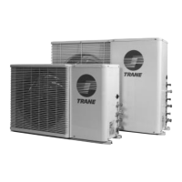
2. Locate supply cover. Apply ¼ in. (6mm.) continuous
bead of 500°F RTV sealant to the flange as shown.
3. Position duct cover as shown, rotate 90 degrees to
allow entrance into supply opening.
4. Slide duct covers into duct openings until inward edge
of duct cover engages with the 2 retaining clips on the
duct flanges. Secure the outward edge of each duct
cover with 2 screws.
5. Slide RETURN DUCT COVER (insulation side up) into
supply opening until inward edge of duct cover
engages with the 2 retaining clips on the duct flange.
Secure outward edge of the duct cover with two
screws.
Horizontal Discharge Conversion
(6 Through 10 Ton Units)
Supplies Needed by Installer for Conversion: 3 oz. tube of
high Temperature RTV sealant. (500°F / 260°C: Similar to
Dow Corning 736)
Note: Failure to use recommended sealant could result in
unit performance loss.
If a unit is to be converted to a Horizontal discharge, the
following conversion must be performed:
1. Remove RETURN and SUPPLY duct covers.
2. Place SUPPLY DUCT COVER over down-flow return
opening. (insulation side down)
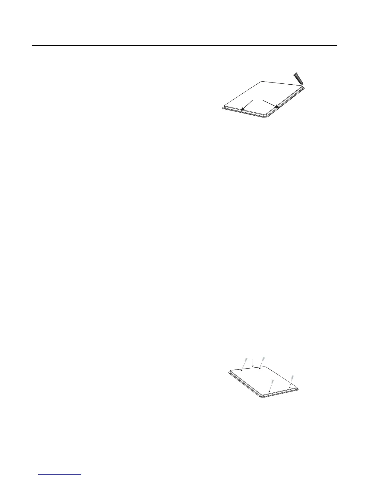
3. Using self-drilling screws, (or screws removed from
duct cover), screw through dimples to attach DUCT
COVER to base.
4. On original RETURN DUCT COVER, apply ¼”(6mm.)
continuous bead of 500°F RTV sealant around flange
(opposite insulation side), as shown.
Figure 18.
Figure 19.
Supply Duct Cover
Screw into 4
dimples on top
edge