12 TTA-SVN03A-EN
.
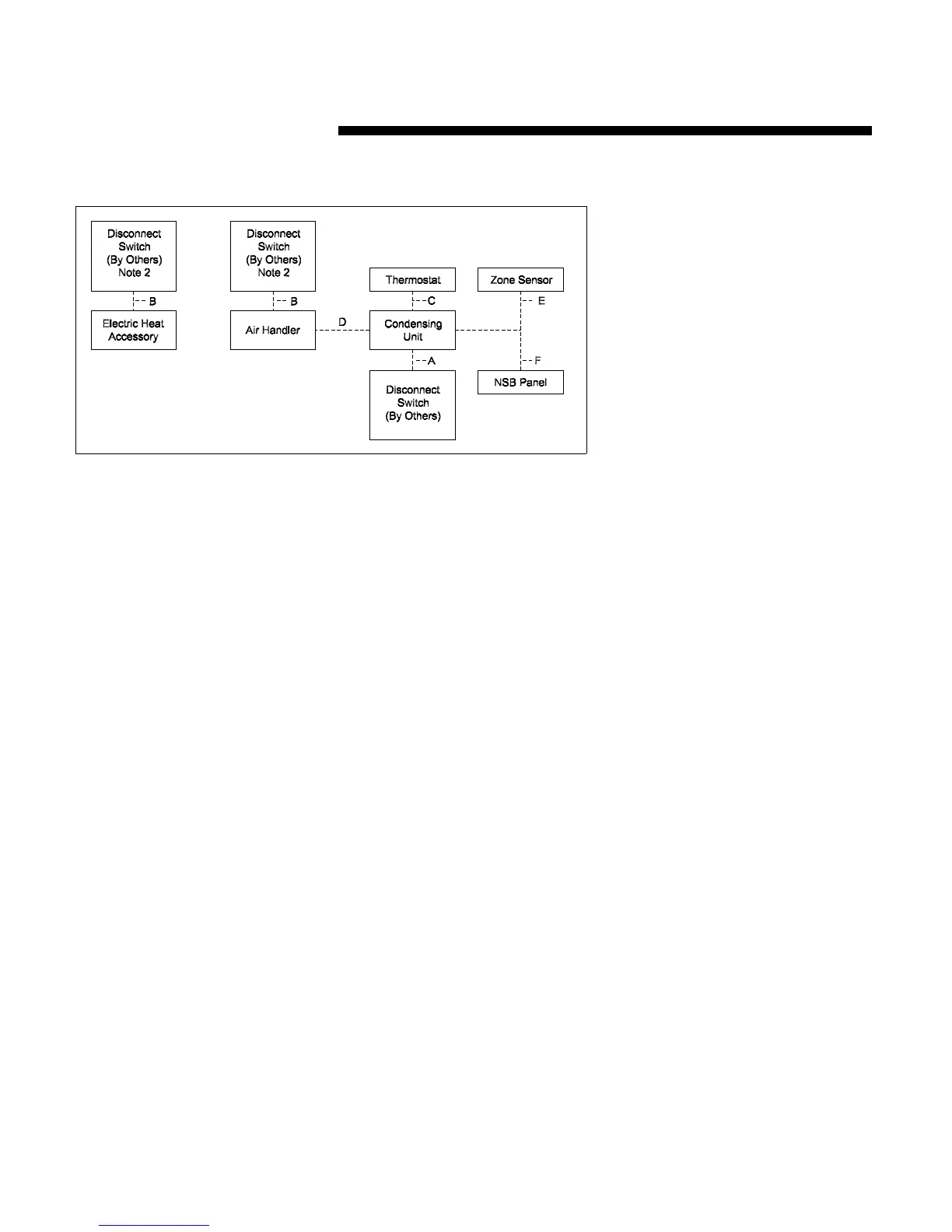
TTA240F/TWE240E
Field Wiring:
A 3 power wires, line voltage
B 3 power wires, line voltage for 3
phase; 2 wires for single phase
C Cooling only thermostat: 5 wires,
24 volts***
– One stage electric heat: add 1
additional wire, 24 volts
– Two stage electric heat: add 2
additional wires, 24 volts
D Add 4 wires, 24 volts
– One stage electric heat: add 1
additional wire, 24 volts
– Two stage electric heat: add 2
additional wires, 24 volts
E Zone Sensor: 2 wires minimum or
10 wires maximum, 24 volts***
(# of wires are dependent upon
zone sensor selection)
F NSB Panel: 8 wires, 24 volts***
Figure 6. Typical Field Wiring - ReliaTel Control
Note: 1) Wiring shown with dashed
lines is to be furnished
and installed by the
customer. All customer
supplied wiring must be
copper only and must
conform to NEC and local
electrical codes. Codes
may require line of sight
between disconnect
switch and unit.
2) When electric heater
accessory is used, single
point or dual point power
entry is optional, since
single point power option
is through electric heater
only.
3) ***Note: Choose only 1 of
the following:
–thermostat
– zone sensor
– night setback panel
Installation
 Loading...