6
12
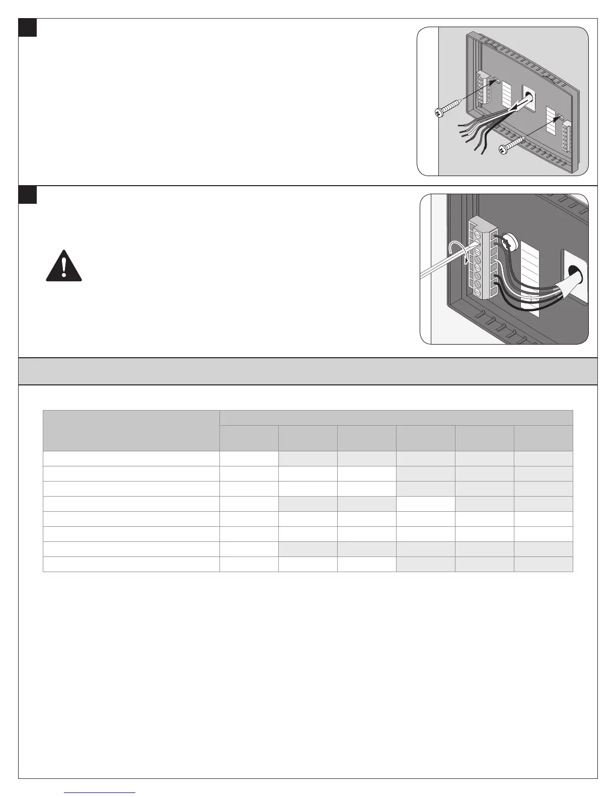
Attach all wires securely to the new thermostat.
(See the Field Wiring Diagrams on the following page.)
Note: A wire must be connected to “24COM” to power the thermostat.
a. Use the information from step 6 to match the wires to the correct terminals.
b. Use 1/8” blade screwdriver to secure wires in terminals.
CAUTION: EQUIPMENT DAMAGE HAZARD
Improper wiring can lead to equipment damage. Follow the Terminal Connection
information from step 6 carefully to ensure the control is wired properly. After wires are
secure, bare wires MUST NOT touch each other. See the Field Connection Wiring
Diagrams on the following pages for specific system applications.
24C
24RC
24RH
W1
W2/0
G
Y1
Y2
RS1
RS1
RS2
RS2
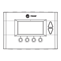
Field Wiring Diagrams - TZEMT500
11
Install new wall plate.
a. Pull wires through hole in center of wall plate.
b. Locate the new wall plate over existing opening.
c. Attach wall plate to wall using two screws provided. Do not overtighten.
24C
24RC
24RH
W1
G
Y1
RS1
RS1
RS2
RS2
W2/0/B
Y2
The following table can be used to find the correct field connection wiring diagram for the HVAC System Type that is being installed.
Indoor Unit Outdoor Unit
1 Stage
Cooling
2 Stage
Cooling
2 Step
Cooling
1 Stage
Heat Pump
2 Stage
Heat Pump
2 Step Heat
Pump
1 or 2 Stage Gas Furnace (PSC/CTM) A NA NA NA NA NA
2 Stage VSPD Gas Furnace A A B NA NA NA
COM Furnace A A A NA NA NA
Air Handler (PSC/CTM) A NA NA C NA NA
VSPD Air Handler A A B C C D
COM Air Handler A A A C C C
Oil Furnace (PSC) E NA NA NA NA NA
VSPD Oil Furnace E E F NA NA NA