ECM Overview and Setup
UNT-SVX07J-EN 77
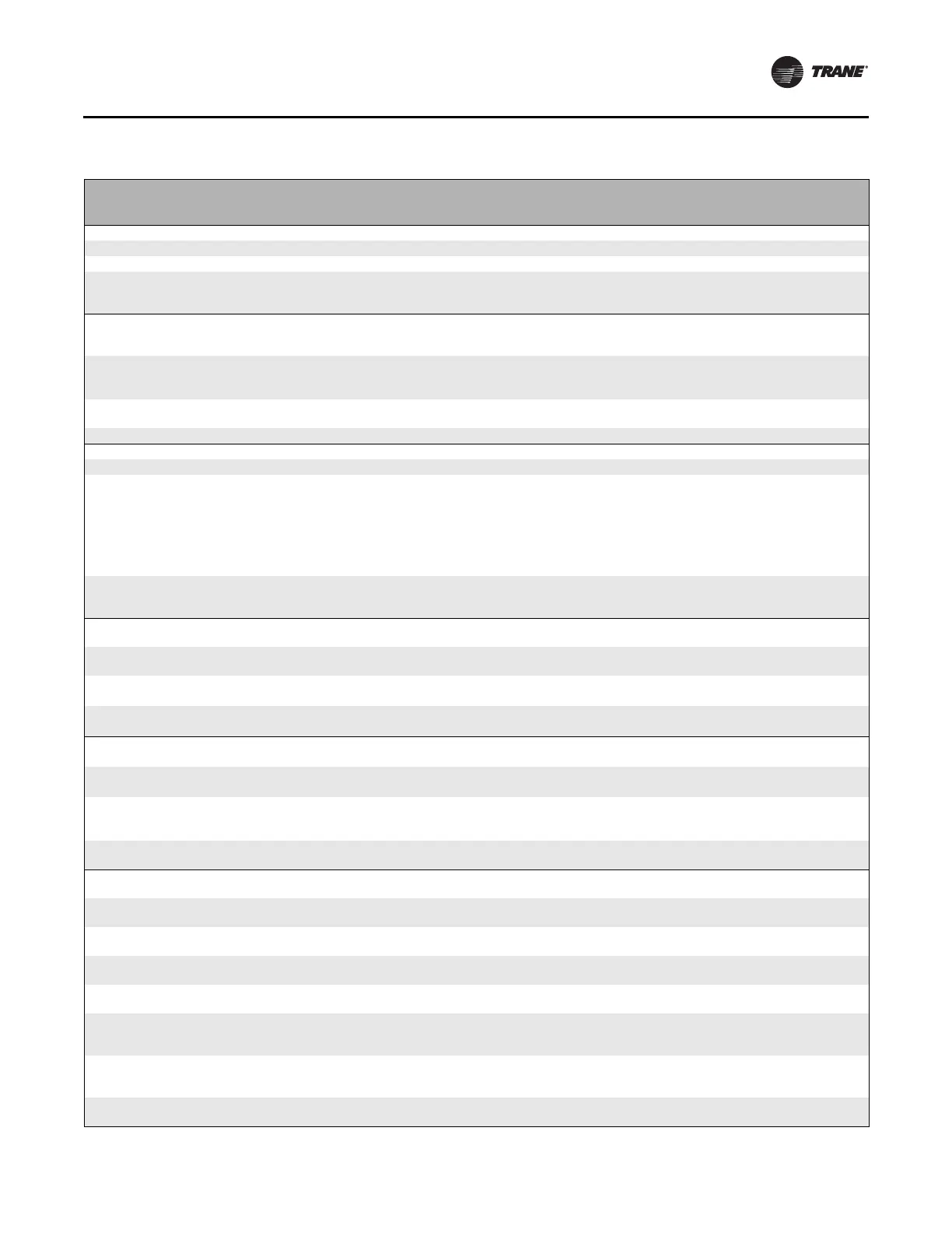
Table 38. Configuration settings of the motor control board (for reference only)
Description on
Unit Label
User
Interface
Name
Typical User
Interface
Value Description
Mtr 1 High Spd Hi 1 1080 Sets the high-speed rpm for Motor 1. Do not exceed 2300 rpm.
Mtr 1 Med Spd md 1 777 Sets the medium-speed rpm for Motor 1.
Mtr 1 Low Spd lo 1 632 Sets the low-speed rpm for Motor 1. Do not set under 600 rpm.
EHStg1 Mtr1 Spd E1m1 0
Assigns an rpm to be associated with a call for
1
st
stage electric heat, for Motor 1 (only on units
equipped with electric heat).
E1M1, E1M2, E2M1, E2M2 settings
are locked out on units with electric heat.
EH Stg 2 Mtr 1 Spd
E2m1 0
Assigns an rpm to be associated with a call for
2
nd
stage electric heat, for Motor 1 (only on
electric heat equipped units).
AI High Spd Mtr 1 ahm1 0
Sets the maximum rpm for Motor 1 for the
maximum input value of the analog input.
Analog inputs below the vFlr setting will be
rejected.
AI Low Spd Mtr 1
alm1 0
Sets the minimum turn-on rpm for Motor 1,
when the analog input becomes active.
Mtr 2 Hgh Spd Hi 2 0 Sets the high-speed rpm for Motor 2. Blower coils have only one motor.
Mtr 2 Med Spd
Md 2 0 Sets the medium-speed rpm for Motor 2.
Mtr 2 Low Spd Lo 2 0 Sets the low-speed rpm for Motor 2.
EHStg1 Mtr2 Spd E1m2 0
Assigns an rpm to be associated with a call for
1
st
stage electric heat, for Motor 2 (only on
electric heat equipped units).
If the unit has only one motor, all seven speed
settings for the second motor
(Hi 2, Md 2, Lo 2, E1M2, E2M2,
ALM2,
AHM2) should be set to zero.
EH Stg 2 Mtr 2 Spd E2m2 0
Assigns an rpm to be associated with a call for
2
nd
stage electric heat, for Motor 2 (only on
electric heat equipped units).
AI High Spd Mtr 2 ahm2 0
Sets the maximum rpm for Motor 2 for the
maximum input value of the analog input.
AI Low Spd Mtr 2 alm2 0
Sets the minimum turn-on rpm for Motor 2,
when the analog input becomes active.
Op Mode Mtr 1 mod1 rpm Sets the operational mode for Motor 1.
Must be set to
rpm for blower coil units.
Op Mode Mtr 2 mod2 rpm Sets the operational mode for Motor 2.
Must be set to rpm for blower coil units.
Mtr 1 Out Format
sig1 pwM
Sets the interface type for Motor 1.
Must be set to
PWM for blower coil units.
Mtr 2 Out Format sig2 pwM Sets the interface type for Motor 2
Must be set to PWM for blower coil units.
Mtr 1/2 PWM Freq.
freq 100
Sets the PWM frequency, for cases when the
PWM outputs are used.
On blower coil units, the
PWM must not be
changed.
Mtr 1 PWM Volt M1vl 5
Sets the PWM voltage, for cases when the PWM
outputs are used.
This setting must NOT be changed, as damage to
the motor may occur!
Mtr 2 PWM Volt
M2vl 5
Sets the PWM voltage, for cases when the PWM
outputs are used.
This setting must NOT be changed, as damage to
the motor may occur!
Mt1 Hgh PWM Lt M1hi 90
Sets the maximum output percentage that the
controller will request from Motor 1.
This envelope protection value should not be
altered.
Mt1 Low PWM Lt
M1Lo 14.5
Sets the minimum maximum output percentage
that the controller will request from Motor 1.
This envelope protection value should not be
altered.
Mt2 Hgh PWM Lt M2hi 90
Sets the maximum output percentage that the
controller will request from Motor 2.
This envelope protection value should not be
altered.
Mt2 Low PWM Lt
M2Lo 14.5
Sets the minimum maximum output percentage
that the controller will request from Motor 2.
This envelope protection value should not be
altered.
Mt1 Ovspd RPM rpm1 2500
Selects the rpm above which the Motor 1 will be
assumed to be in an overspeed condition and will
need to be shut down.
This envelope protection value should not be
altered.
Mt2 Ovspd RPM
rpm2 2500
Selects the rpm above which the Motor 2 will be
assumed to be in an overspeed condition and will
need to be shut down.
This envelope protection value should not be
altered.
Fan Proving Fct FPrv Fnst
Selects which mode should be assigned to the
Binary output circuit, depending on unit type.
This setting has to be correct for proper unit
operation of electric heat and changeover units.