Coil Piping and Connections
UNT-SVX07J-EN 55
Condensate Drain Connections
1. Connect a 3/4-inch I.D. rubber or plastic hose to the
auxiliary drain pan. This should be a mechanical
connection that allows easy removal of the auxiliary
drain pan when servicing the piping end pocket.
2. Slide the hose over the drain pan nipple and tighten the
hose on the nipple with a hose clamp (installer
supplied).
3. Maintain a continuous drain line pitch of one inch per
ten feet of drain line run to provide adequate
condensate drainage. Extend the drain line straight
from the drain pan a minimum distance of six inches
before making any turns. The installer must provide
proper support for the drain line to prevent undue
stress on the auxiliary drain pan.
4. Install a secondary overflow drain line if necessary by
punching out the overflow drain nipple on the auxiliary
drain pan. Next, place a 3/8-inch inside diameter
flexible plastic tube over the nipple and secure with a
field supplied hose clamp.
Note: The installer is responsible for adequately
insulating field piping. See “External Insulating
Requirements,” p. 56 for more information.
Condensate Overflow Detection Device
The condensate overflow detection device is an option on
fan-coil units with either a Tracer® ZN010, ZN510, ZN520,
UC400-B, or the customer-supplied control interface. The
float switch, mounting bracket, and coiled leads ship
attached inside the piping end pocket of the unit. Install the
switch by placing the hole or slot in the bracket over the
condensate overflow drain (of the auxiliary drain pan) with
the switch float extending over the pan. Secure the drain
pan by attaching the pan’s bracket with the factory
provided clip. See the figures below.
Entering Water Temperature Sensor
Two-pipe changeover units with either the Tracer® ZN010,
ZN510, ZN520, and UC400-B and CSTI controls have an
entering water temperature sensor that senses supply
water temperature. On units with a factory piping package,
the factory straps the entering water temperature sensor
to the piping supply water pipe.
Tracer® Controls use entering water temperature
sampling eliminating the need for entering water
temperature sensor relocation. If there are problems
sensing accurate temperature for non-flowing water,
move entering water temperature sensor as far down the
supply line as possible to get accurate water temperatures.
See the figures below.
Figure 28. Condensate float switch installed in
horizontal auxiliary drain pan
Figure 29. Condensate float switch installed in vertical
auxiliary drain pan
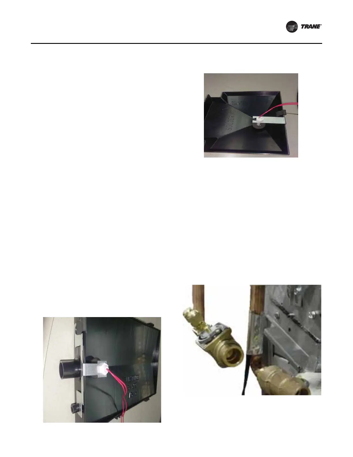
Figure 30. Attach the entering water temperature
sensor to the entering water pipe as shown
for changeover to work properly