18-BC92D1-1F-EN
5
Unit Location Considerations
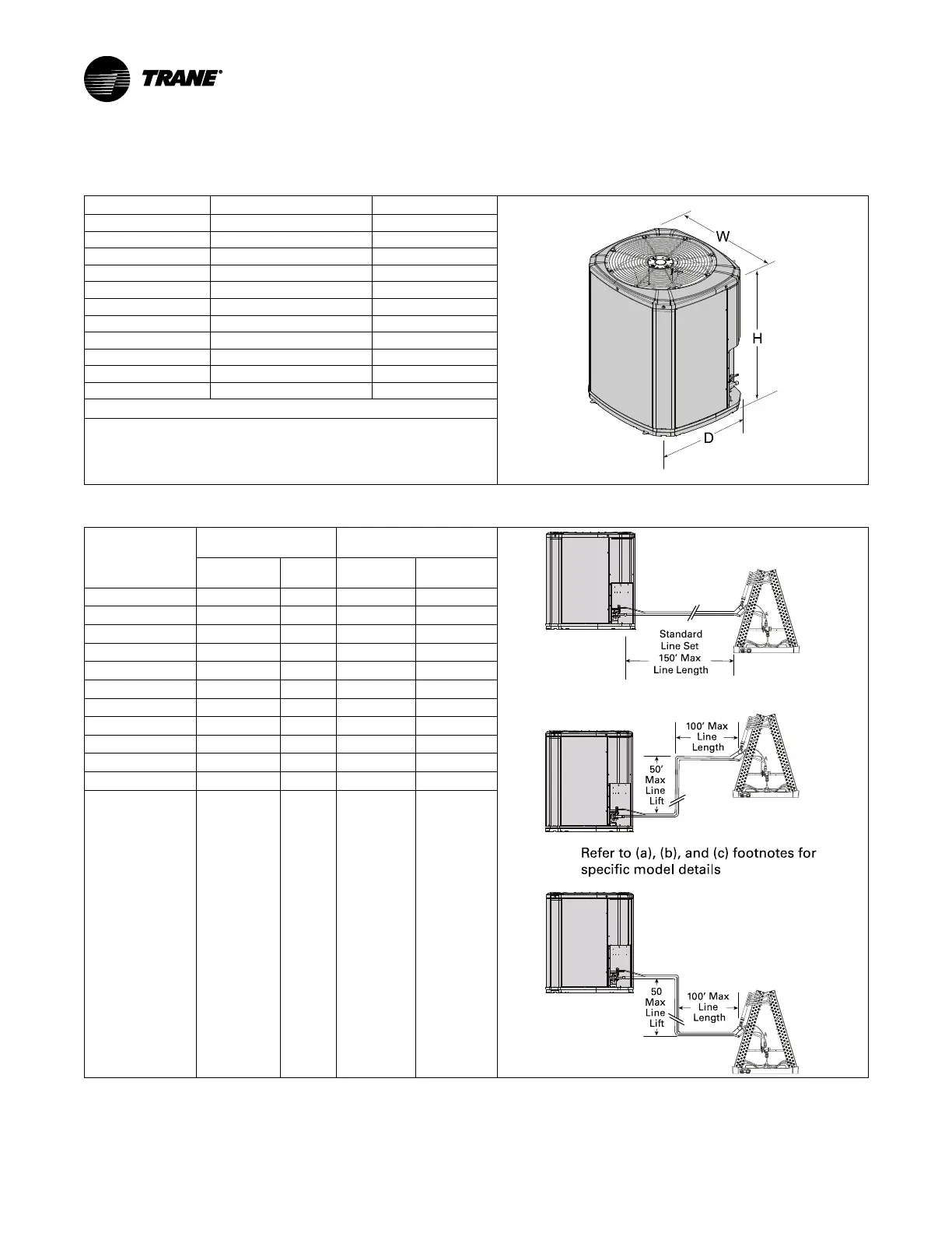
Table 2. Unit Dimensions and Weight
Models
H x D x W (in) Weight * (lb)
4TWV8024A 41 x 30 x 33 195
4TWV8036A 41 x 30 x 33 208
4TWV8037A 41 x 34 x 37 229
4TWV8048A 41 x 34 x 37 234
4TWV8049A 41 x 34 x 37 241
4TWV8060A 45 x 34 x 37 250
4TTV8024A 41 x 30 x 33 196
4TTV8036A 41 x 30 x 33 207
4TTV8037A 41 x 34 x 37 225
4TTV8048A 41 x 34 x 37 245
4TTV8060A 45 x 34 x 37 250
* Weight values are estimated (uncrated).
• When mounting the outdoor unit on a roof, be sure the roof will
support the unit’s weight.
• Properly selected isolation is recommended to alleviate sound or
vibration transmission to the building structure.
Table 3. Refrigerant Line and Service Valve Connection Sizes
Model
Rated Line Sizes
Service Valve
Connection Sizes
50’
Ma
x
Line
Lift
Sta ndard
Line S
et
150’ Max
Line Length
50
Max
Line
Lift
100’
M
ax
Line
Length
100’ Max
Line
Length
Refer to (a), (b), and (c) footnotes for
specific m odel details
Vapor
Line
Liquid
Line
Vapor Line
Connection
Liquid Line
Connection
4TWV8024A
5/8
(a)
3/8 3/4 3/8
4TWV8036A
3/4
(a)
3/8 3/4 3/8
4TWV8037A
3/4
(a)
3/8 3/4 3/8
4TWV8048A
7/8
(a)
3/8 7/8 3/8
4TWV8049A
7/8
(a)
3/8 7/8 3/8
4TWV8060A
1—1/8
(b)
3/8 7/8 3/8
4TTV8024A
5/8
(a)
3/8 3/4 3/8
4TTV8036A
3/4
(a)
3/8 3/4 3/8
4TTV8037A
3/4
(a)
3/8 3/4 3/8
4TTV8048A
7/8
(a)
3/8 7/8 3/8
4TTV8060A
1—1/8
(c)
3/8 7/8 3/8
(a)
The max length of refrigerant lines from outdoor to indoor unit MUST NOT exceed 150 feet. The max vertical change MUST NOT exceed 50 feet.
(b)
The max length of refrigerant lines from the outdoor to indoor unit MUST NOT exceed 80 feet. The max vertical change MUST NOT exceed 10 feet.
(c)
The max length of refrigerant lines from outdoor to indoor unit MUST NOT exceed 80 feet. The max vertical change MUST NOT exceed 25 feet.
 Loading...