18-BC92D1-1F-EN
17
Electrical — Low Voltage
Table 23, p. 17defines the size and combined total maximum length of low voltage wiring from the outdoor unit, to the indoor unit, and to the
thermostat.
Note: The use of color coded low voltage wire is recommended to simplify connections between the outdoor unit, the control, and the indoor
unit.
Note: The maximum total cable length for the entire comfort control communicating system is 500 ft. 18 AWG.
Table 23. Low Voltage Maximum Wire Length
CONTROL WIRING
WIRE SIZE MAX. WIRE LENGTH
18 AWG 500 Ft. Combined
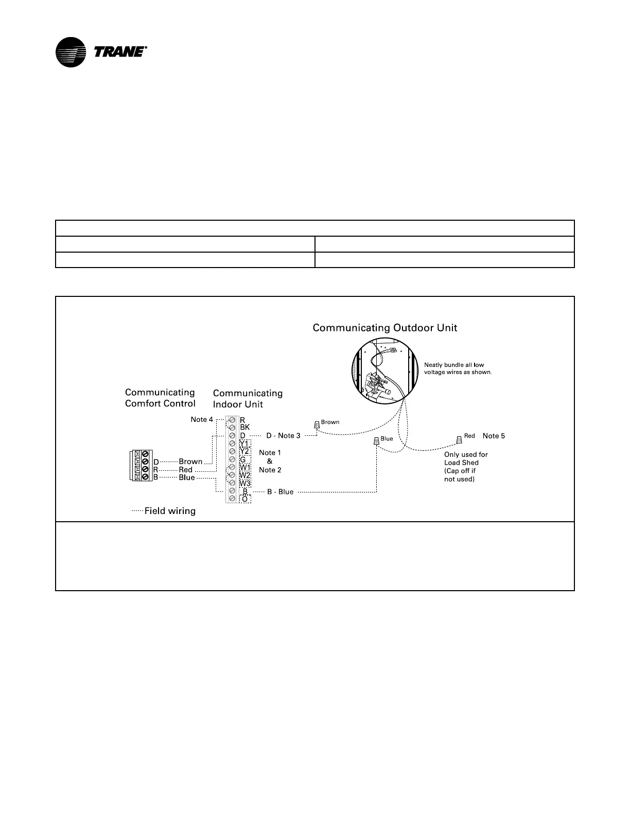
Table 24. Low Voltage Hook-up Diagrams
Figure 1. Fully Communicating System
Neatl y bundle all low
voltage wires as shown.
Com m unicating
Com for t Cont rol
W1
W2
W3
G
Y2
B
O
BK
D
Y1
R
Field wiring
Bro wn
Blue
Bro wn
Blue
Red
B - Blue
D - Note 3
D
R
B
Note 1
&
Note 2
Red
Only used for
Load Shed
(Cap off if
not used)
Com m unicating
Indoo r Unit
Note 4
Note 5
Com municating Outdoor Unit
1. In communicating mode, unused terminals are non-functional. Do not use.
2. Terminals present will vary by indoor model.
3. “D” is the data line. Installer to select a wire color.
4. If a 3rd party condensate overflow switch is installed, it should be wired in series with R to the thermostat or connected to the External
Switch terminals on the AFC. See External Switch wiring section in the air handler Installer’s Guide.
5. Wire present only on Variable Speed Outdoor Units.
Note: Anti-oxidizing grease is supplied in the documentation package for use when making low voltage field wiring connections at the outdoor
unit. Apply grease to field wiring before installing wire caps to protect these connections from corrosion.
 Loading...