Unit Weights
RT-SVX25Q-EN 19
Rigging
WARNING
Heavy Objects!
Failure to follow instructions below could result in unit
dropping which could result in death or serious injury,
and equipment or property-only damage.
Ensure that all the lifting equipment used is properly
rat
ed for the weight of the unit being lifted. Each of the
cables (chains or slings), hooks, and shackles used to
lift the unit must be capable of supporting the entire
weight of the unit. Lifting cables (chains or slings) may
not be of the same length. Adjust as necessary for even
unit lift.
WARNING
Improper Unit Lift!
Failure to properly lift unit in a LEVEL position could
result in unit dropping and possibly crushing operator/
technician which could result in death or serious injury,
and equipment or property-only damage.
Test lift unit approximately 24 inches (61 cm) to verify
p
rop
er center of gravity lift point. To avoid dropping of
unit, reposition lifting point if unit is not level.
Refer to Figure 10, p. 19 and Table 1, p. 18 and Table 2,
p. 18 for typical unit operating weights rigging before
pr
oceeding
.
1. Remove the shipping crate from arou
nd the unit. Do
not remove the crating from the top of the unit.
2. Rig the unit as shown in Figure 10, p. 19. Attach
adequate strength lifting sling
s to all four lifting
brackets in the unit base rail. Do not use cables, chains,
or slings except as shown.
3. Install a lifting bar,
as shown in Figure 10
, p. 19, to
protect the unit and to facilitate a uniform lift. The
minimum distance between the lifting hook and the
top of the unit should be 7 feet.
NOTICE
Unit Damage!
Unit damage will occur if fork lifting is attempted once
the pallet has been removed.
4. Removal of the base pallet must be completed before
unit can
be set. Prior to lifting the unit, remove the 6
fork pockets from the base rails and 4 wood screws
from the lifting lug corners. The unit will then separate
from the pallet when lifted.
5. Test-lift the unit to ensure it is properly rigged and
balanced, make any
necessary rigging adjustments.
6. Lift the unit and position it into place.
7. Downflow units; align the base
rail of the unit with the
curb rail while lowering the unit onto the curb. Make
sure that the gasket on the curb is not damaged while
positioning the unit.
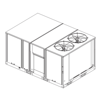
Figure 10. Rigging and center of gravity data
TOP CRATING
CENTER OF GRAVITY
LENGTH
CENTER OF
GRAVITY WIDTH
RIGGING
 Loading...


