30 RT-SVX25Q-EN
Factory-Mounted Unit Options
Circuit Breaker (FIYUCB) and Unit
Disconnect (FIYUDC)
WARNING
Hazardous Voltage w/Capacitors!
Failure to disconnect power and discharge capacitors
before servicing could result in death or serious injury.
Disconnect all electric power, including remote
d
isconnects and discharge all motor start/run
capacitors before servicing. Follow proper lockout/
tagout procedures to ensure the power cannot be
inadvertently energized. Verify with a CAT III or IV
voltmeter rated per NFPA 70E that all capacitors have
discharged.
WARNING
Proper Field Wiring and Grounding
Required!
Failure to follow code could result in death or serious
injury.
All field wiring MUST be performed by qualified
personnel.
Improperly installed and grounded field
wiring poses FIRE and ELECTROCUTION hazards. To
avoid these hazards, you MUST follow requirements for
field wiring installation and grounding as described in
NEC and your local/state/national electrical codes.
Important: All pha
ses of this installation must comply
with NATIONAL, STATE, and LOCAL
CODES. In addition to local codes, the
installation must comply with National
Electric Code - ANSI/NFPA NO. 70 LATEST
REVISION.
1. Field connections are made
by first removi
ng all
access panels on the front of the unit. Unscrew the
assembly around the outside of the disconnect switch
or circuit breaker. This assembly is located between
the evaporator and heat section of the unit (Figure 18,
p. 30).
For downflow configurations, the hole in the base
secti
on is for both high and low voltage power wiring
on down flow units. Horizontal units will route through
the front plate located directly under the circuit breaker
or disconnect panel. The hole is sized for 1 1/2" conduit.
Horizontal units will use the front plate located directly
under the circuit breaker panel.
2. If the conduit required for you
r application is larger,
remove the termination plate and connect to the larger
hole using field supplied reducing washers.
3. Route the power wires and ground conductor through
conduit and into
the bottom of the
factory installed
disconnect switch or circuit breaker. Connect the
power conductors to the lugs provided. Connect the
ground wire to the unit ground lug.
Note: Wire size for the length of run should be
determined u
sing the circuit ampacity found on
the unit nameplate and the N.E.C.
4. Route low voltage (class II), control
wiring through
hole in base of unit but not through high voltage
conduit. Feed control wiring through bushing provided
on side panel and into the flexible conduit provided in
the heat section of the unit (Figure 18). Route wires
th
rough lo
ose wire ties provided in unit as in Figure 18.
5. Tighten the wire ties. Secure the exce
ss wire bundle
under the wire ties in the outdoor section. Do not leave
excess wire in the electrical enclosure. Use the unit
wiring diagram to make the low voltage connections.
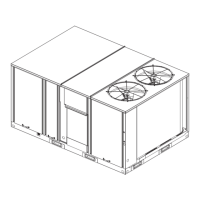
Figure 18. Main power entrance for units with factory
mounted disconnect or circuit breaker
 Loading...


