RT-SVX23D-EN 29
Installation
Filter Installation
Each unit ships with filters installed. The quantity of filters is determined by unit size. Access to the
filters is obtained by removing the indoor fan access panel. To modify the 3, 4 or 5 ton unit’s filter
rack to accept two inch filters, remove the L-shaped angle attachment screws and rotate the angles
90 degrees.
Reinstall the screws and insert new filters. Refer to the unit Service Facts (shipped with each unit)
for filter requirements.
Note: Do not operate the unit without filters.
Field Installed Power Wiring
An overall dimensional layout for the field installed wiring entrance into the unit is illustrated in
“Unit Clearances,” p. 13. To insure that the unit’s supply power wiring is properly sized and
installed, follow the guidelines outlined below.
Note: All field installed wiring must conform to NEC guidelines as well as State and Local codes.
Verify that the power supply available is compatible with the unit’s nameplate ratings. The available
supply power must be within 10% of the rated voltage stamped on the nameplate. Use only copper
conductors to connect the power supply to the unit.
NOTICE
Use Copper Conductors Only!
Unit terminals are not designed to accept other types of conductors. Failure to use copper
conductors may result in equipment damage.
Note: If the unit is not equipped with an optional factory installed nonfused disconnect switch or
circuit breaker, a field supplied disconnect switch must be installed at or near the unit in
accordance with the National Electrical Code (NEC latest edition).
Main Unit Power Standard Wiring
1. Location of the applicable electrical service entrance is illustrated in “Unit Clearances,” p. 13.
Complete the unit’s power wiring connections at Compressor Contactor # 1 (CC1) inside the unit
control panel. Refer to the customer connection diagram that is shipped with the unit for
specific termination points.
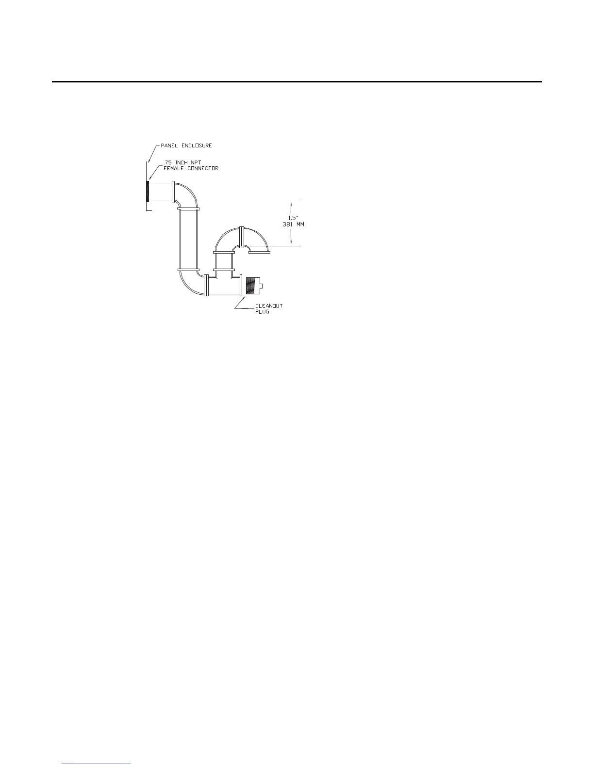
Figure 21. Condensate Trap Installation