30 RT-SVX23D-EN
Installation
2. Provide proper grounding for the unit in accordance with local and national codes.
Main Unit Power Optional TBUE Wiring (Through the Base Electrical Option)
1. Location of the applicable electrical service is illustrated below. Refer to the customer
connection diagram that is shipped with the unit for specific termination points. The
termination points, depending on the customer option selected would be a factory mounted
nonfused disconnect switch (UDC) or circuit breaker (UCB). If neither a factory mounted
nonfused disconnect switch (UDC) or circuit breaker (UCB) was factory mounted, field wiring
connections should be terminated in the control box at Compressor Contactor # 1 (CC1).
2. Provide proper grounding for the unit in accordance with local and national codes.
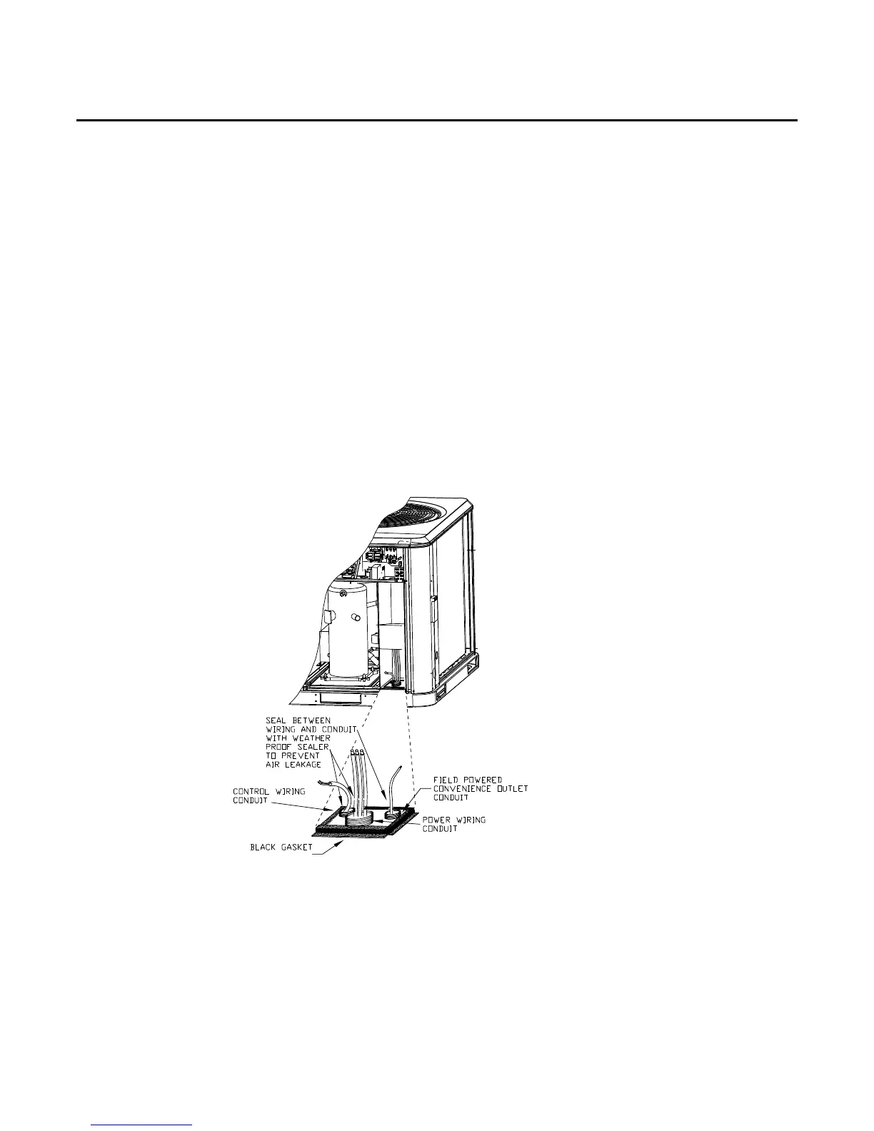
Note: Black Gasket is shipped from the factory and is located in the literature Ship With bag in the
control box. Apply Black Gasket around conduit plate on all 4 sides after installation to
prevent air leakage from the building entering the electrical enclosures.
Note: Seal between wiring and conduit with Black Gasket or weather proof sealer to prevent air
leakage from the building entering the electrical enclosures. Also seal around conduit and
wiring at all roof and curb penetrations.
Field Installed Control Wiring
An overall layout of the various control options available with the required number of conductors
for each control device is illustrated in Figure 28, p. 36.
Note: All field wiring must conform to NEC guidelines as well as state and local codes.
Figure 22.