22 RT-SVX23D-EN
Installation
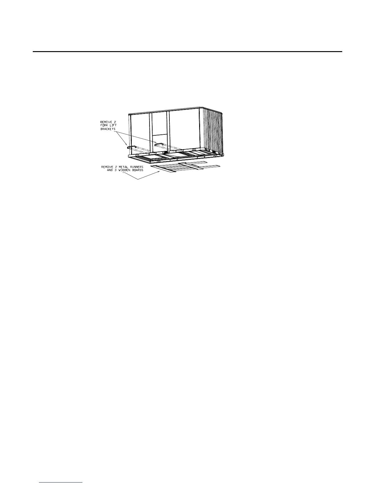
6. Lift the unit enough to allow the removal of two Fork Lift brackets and hardware. Remove the
two Fork Lift brackets, two metal runners and three wooden boards as shown in the following
Figure.
7. Downflow units; align the base rail of the unit with the curb rail while lowering the unit onto
the curb. Make sure that the gasket on the curb is not damaged while positioning the unit.
General Unit Requirements
• The checklist listed below is a summary of the steps required to successfully install a
commercial unit. This checklist is intended to acquaint the installing personnel with what is
required in the installation process. It does not replace the detailed instructions called out in the
applicable sections of this manual.
• Check the unit for shipping damage and material shortage; file a freight claim and notify
appropriate sales representative.
• Verify correct model, options and voltage from unit nameplate.
• Verify that the installation location of the unit will provide the required clearance for proper
operation.
• Assemble and install the roof curb (if applicable). Refer to the latest edition of the curb installers
guide that ships with each curb kit.
• Fabricate and install ductwork; secure ductwork to curb.
• Rigging the unit.
• Set the unit onto the curb; check for levelness.
• Ensure unit-to-curb seal is tight and without buckles or cracks.
• Install and connect a condensate drain line to the evaporator drain connection.
Factory Installed Economizer
• Ensure the economizer has been pulled out into the operating position. Refer to the economizer
installers guide for proper position and setup.
• Install all access panels.
Temperature Limit Switch Usage for Electric Heat Units
Units are factory shipped in the downflow discharge confriguration but can be field converted to
a horizontal discharge confriguration. Some, but not all units require a different TC0-A limit switch,
which is wire tied near the terminal block in the heater compartment if horizontal discharge
confriguration is used.
Figure 12. Fork lift pockets