BAS-SVX04A-EN • Wireless Zone Sensor 19
Setting the Address, Mounting, Wiring, and Associating the
Receiver and Sensor
Table 2. Wiring harness: Wire identification
Wire label Color Function
HEATING SET N/A Not used. For future use.
FAN/SYSTEM N/A Not used. For future use.
SETPOINT Red Space temperature setpoint
ZONE White Zone temperature
GND-SIGNAL
i
Black Ground for setpoint and zone signal
24VAC/DC Blue 24 Vac/Vdc power
GND-POWER
a
Yellow Ground for 24 Vac/dc
COMM + N/A Not used. For future use.
COMM – N/A Not used. For future use.
i
Both GND-SIGNAL and GND-POWER must be wired for the receiver to operate (see Figure 8, p. 22 or
Figure 9, p. 23).
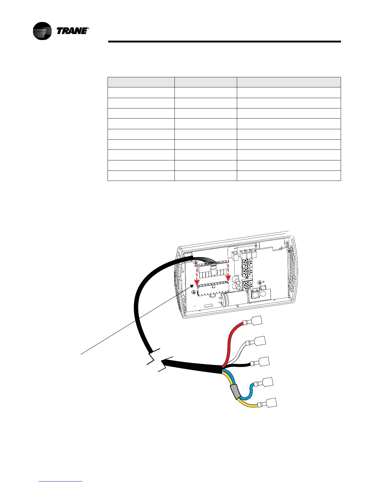
Figure 5. Wiring harness
SETPOINT
ZONE
GND-SIGNAL
24 VAC/DC
GND-POWER
Red
White
Black
Blue
Yellow
RECEIVER
Connect wiring
harness to
receiver

 Loading...