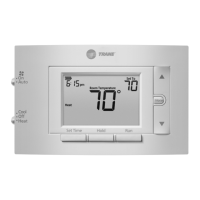
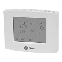
The Trane XR202 Programmable Thermostat (TCONT202AS11MA) is a single-stage, push-button thermostat designed for climate-controlled living spaces. It features a 3.5-inch backlit display and offers flexible scheduling options, including 7-day, 5-1-1 day programs, or a non-programmable mode. This device is suitable for various HVAC systems, including Gas, Oil, Electric, (mV and 24V), Heat Only, Cool Only, or Heat/Cool systems, supporting a maximum of 1 Heat (1H) and 1 Cool (1C) stage.
Function Description:
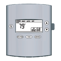
The thermostat allows users to control heating and cooling systems, set desired temperatures, and program schedules to optimize energy efficiency and comfort. It includes a fan switch with "On" and "Auto" settings, and a system switch for "Cool," "Off," and "Heat" modes. The device provides a "Hold" function for permanent temperature settings, a "Program Override" for temporary adjustments, and a "Keypad Lockout" to prevent unwanted changes. An "Early Start" feature can be enabled to ensure the programmed temperature is reached by the scheduled time.
Important Technical Specifications:
- Product Model: TCONT202 / XR 202
- Size: 3-3/4" H x 6" W x 1-1/8" D
- Configurations: Heat / Cool (1H, 1C)
- Operating Temperature: 32°F to 105°F (0 to +41°C) / 90% RH Non-Condensing
- Shipping Temperature Range: -20°F to 150°F (-29 to +65°C)
- Input Power (DC): Two 1.5V AA Alkaline batteries
- Input Power (AC): 20 - 30 VAC, NEC Class II, 50/60 Hz
- Wire Usage: 18 AWG
- System Modes: Heating, Cooling, Off
- Fan Modes: Auto, On
- Cooling Setpoint Temperature Range: 45°F to 99°F (1°F resolution)
- Heating Setpoint Temperature Range: 45°F to 99°F (1°F resolution)
- Temperature Display Range: 32°F to 99°F (1°F resolution)
- Minimum Cycle Off Time Delay: Compressor: 5 minutes, Indoor Heat: 1 minute
- Terminal Load: 1.0A per terminal, 1.5A maximum all terminals combined
- Rated Differentials (at 6°F/Hr):
- Heat: Fast (0.5°F), Medium (0.75°F), Slow (1.9°F)
- Cool: Fast (0.9°F), Medium (1.2°F), Slow (1.7°F)
- Display Adjustment: Temperature display can be adjusted +/-5°F or °C.
Usage Features:
- User-Friendly Interface: The thermostat features a clear, backlit display showing current time, room temperature, setpoint, system status (Cool On/Heat On), and battery status.
- Scheduling: Offers 7-day, 5-1-1 day, or non-programmable modes. The factory default schedule is an energy-saving program with specific wake, leave, return, and sleep settings for both heating and cooling.
- Heating Schedule (Factory Default):
- P1/WAKE: 6:00 AM - 70°F
- P2/LEAVE: 8:00 AM - 62°F
- P3/RETURN: 5:00 PM - 70°F
- P4/SLEEP: 10:00 PM - 62°F
- Cooling Schedule (Factory Default):
- P1/WAKE: 6:00 AM - 78°F
- P2/LEAVE: 8:00 AM - 85°F
- P3/RETURN: 5:00 PM - 78°F
- P4/SLEEP: 10:00 PM - 82°F
- Temperature Control: Allows users to raise or lower the temperature setting with dedicated buttons.
- Hold Function: A "Hold" button enables a permanent temperature hold, bypassing the programmed schedule until manually released.
- Temporary Override: Adjusting the temperature during a programmed period initiates a temporary override, which lasts for a minimum of 2 hours or until the next programmed time period.
- Early Start: An optional feature that starts heating or cooling early to ensure the programmed temperature is reached by the scheduled time.
- Continuous Display Light: The backlight can be set to be always on, requiring a "C" wire connection. Otherwise, it illuminates momentarily.
- Fahrenheit/Celsius Selection: Users can choose their preferred temperature unit.
- Keypad Lockout: A security feature to disable buttons and prevent unauthorized changes.
- Installer Menu: Accessible by holding the "Menu" button for 8 seconds, this menu provides advanced settings such as heat/cool cycle rates, compressor lockout, minimum off time, maximum/minimum set points, schedule type, early start, temperature display adjustment, continuous display light, change air filter reminder, and keypad lock.
Maintenance Features:
- Battery Replacement: The thermostat uses two 1.5V AA alkaline batteries. A low battery indicator ("Replace" icon) appears on the display when replacement is needed. For best results, premium brand batteries like Duracell® or Energizer® are recommended. Batteries should be replaced before leaving the home unoccupied for extended periods (over 3 months) if the low battery indicator is displayed.
- Air Filter Reminder: A monthly reminder can be set (1 to 12 months) to prompt users to change the air filter.
- Troubleshooting Guide: The manual provides a comprehensive troubleshooting section for common issues like no heat/cool/fan, constant operation, display discrepancies, and rapid cycling, offering possible causes and corrective actions.
- Reset Functionality: The thermostat can be reset by removing batteries for 2 minutes (retains menu settings and program) or by holding the "Menu" and "Backlight" buttons simultaneously until the display goes blank (resets schedule and user settings to factory defaults).
- Installation must comply with national, state, and local codes.
- Disconnect power to the system at the main fuse or circuit breaker box before installation.
- Do not operate the cooling system if the outdoor temperature is below 55°F to prevent compressor damage.
- Ensure compressor oil heaters have been operational for 6 hours and the system has not been operational for at least 5 minutes before running the compressor.
- The product does not contain mercury, but if replacing an older thermostat, proper disposal of mercury-containing products is advised via www.thermostat-recycle.org.