Installation and User Guide
4 Pub. No. 18HD51D1-1C-EN 09/2020 Part No. 37-7769005
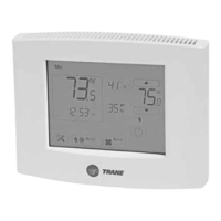
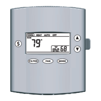
FIGURE 1. PLACEMENT OF THE 202
Incorrect
Placement
Ceiling Fan
Natural heat
dissipation
from the
thermostat
Onboard
Thermistor
5 FEET
Optimum
Zone
2 FEET
Placement
Heat from the screen may be trapped
within the body of the Control by an
external top-down airflow source, such
as a ceiling fan.
The onboard thermistor may be biased
by this heat causing the displayed
indoor temperature to be elevated.
4.2 Mounting / Installation
Follow these steps to mount the 202 Control to the wall.
1. Turn OFF all power to heating and cooling equipment.
2. If an existing thermostat is being replaced:
a. Record color and terminal marking of each wire.
b. Disconnect the wires from the existing thermostat
being careful not to allow them to fall back into the wall.
c. Remove the existing thermostat from the wall.
3. Pull the thermostat body off the thermostat base. Forcing
or prying on the thermostat will cause damage to the unit.
4. Move base over hole in wall and mark mounting hole
locations on wall using base as template. (See Fig. 1)
5. Move base out of the way. Drill mounting holes. If you are
using existing mounting holes pull thermostat wire bundle
through the hole in the thermostat base. Mount sub-base
to wall. Leveling is for appearance only and will not affect
thermostat operation.
6. Connect wires to terminal block on base using appropriate
wiring diagram.
7. Push excess wire into wall and plug hole with a fire resistant
material (such as fiberglass insulation) to prevent drafts
from affecting thermostat operation.
8. Two “AA” alkaline batteries are included in the thermostat
at the factory with a battery tag to prevent power drainage
9. Remove the battery tag to engage the batteries
4.3 Battery Location
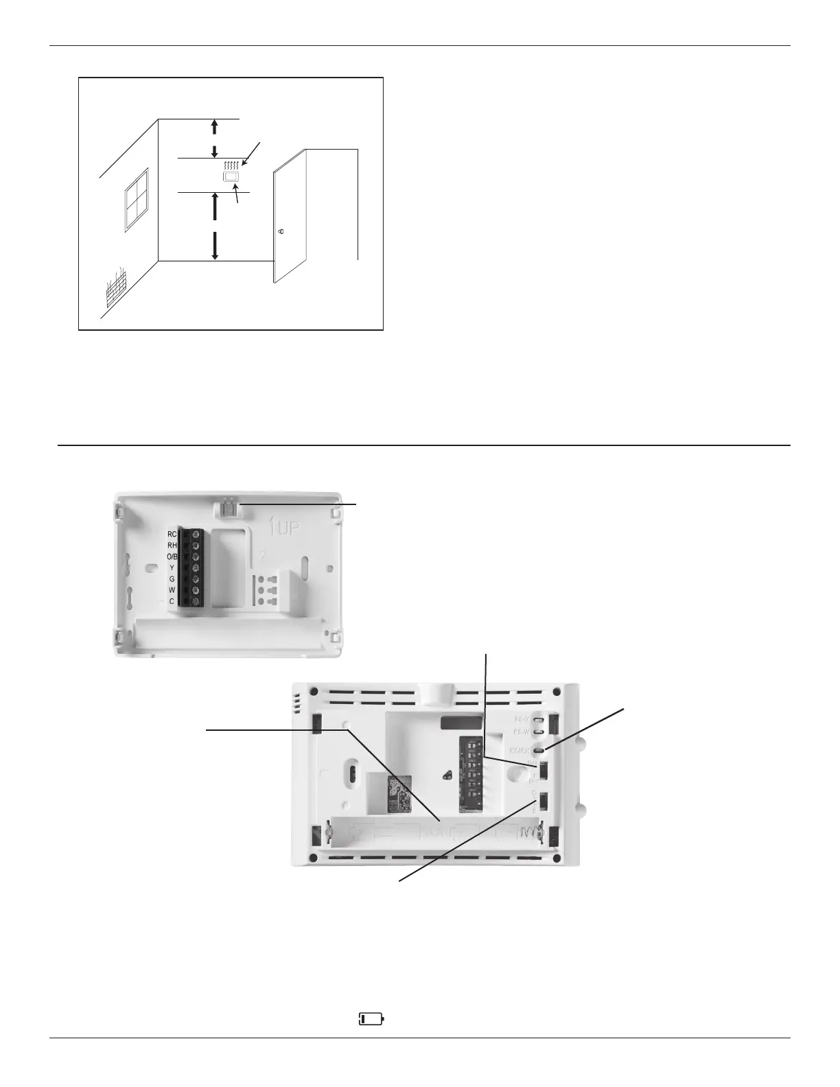
FIGURE 2.
Leveling Thermostat
Leveling is for appearance only and
will not aect thermostat operation.
Battery Location
Premium AA alkaline batteries are
required when C-wire is not available.
When C-wire is available, the batteries
provide a back-up source of power (this
will maintain the clock in the event of a
power outage).
RC/RH Jumper Wire
This thermostat electrically
connects the RC and RH
terminals so a jumper
wire is not required. If the
application provides a
separate wire for RC and
RH, clip the RC/RH jumper.
This will isolate both
terminals so they can be
independently used.
4.4 Battery Replacement
To replace batteries, set system to OFF, remove thermostat from wall and install the batteries in the rear along the top of the thermostat
(see Figure 1). For best results, use a premium brand “AA” alkaline battery such as Duracell
®
or Energizer
®
. If the home is going to be
unoccupied for an extended period (over 3 months) and “
” is displayed the batteries should be replaced before leaving.
IMPORTANT:
• Do not exceed the specification
ratings.
• All wiring must conform to local
and national electrical codes
and ordinances.
• This control is a precision
instrument, and should be
handled carefully. Rough
handling or distorting
components could cause the
control to malfunction
Gas/Electric Switch
If the system is a heat pump or electric
furnace, the GAS/ELEC Switch must be
set to Electric. If your system is a gas or oil
furnace, the switch must be set to Gas.
O/B Terminal Switch
The O/B switch on this thermostat is factory set to the O position. This will accommodate the majority of heat pump applications,
which require the changeover relay to be energized in Cool. If the heat pump being installed requires a B terminal, to energize the
changeover relay in Heat, the O/B switch must be moved to the B position. To enable single stage heat pump operation a jumper
must be eld installed between Y and W. The 202 does not support auxiliary heat.