
D
David ElliottAug 7, 2025
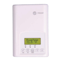
Why is there no display on my Trane X13511542010?
- MmholdenAug 7, 2025
A blank display on your Trane Thermostat can be due to a couple of reasons. First, check the power supply voltage between C and RC to ensure it's within the range of 19-30 Vac. Also, check for any tripped fuses or circuit breakers. Another potential cause is an overloaded power transformer. Make sure the transformer is powerful enough to supply all connected devices, including the thermostat.