Do you have a question about the Trane XT302C and is the answer not in the manual?
Provides electric control of 24 Vac single-zone multistage systems and requires a common wire for power.
Details thermostat model, system, changeover, system selection, fan selection, and comments.
Instructions for recycling thermostats containing mercury, contact local waste management.
Read instructions carefully, check ratings, installer must be trained, verify operation after installation.
Install 5 ft (1.5m) above floor, avoid drafts, heat sources, and unheated areas.
Position wallplate horizontally on wall or wiring box, level for appearance.
Mark holes using pencil, drill 3/16 inch (drywall) or 7/32 inch (plaster) holes, tap in anchors.
Position wallplate, pull wires through, insert and tighten mounting screws.
Disconnect power before wiring to prevent electrical shock or equipment damage.
Loosen terminal screws, connect 18 gauge color-coded cable, tighten screws, push excess wire back.
Plug the wire hole with nonflammable insulation to prevent drafts affecting the thermostat.
Engage tabs at the top of the thermostat and wallplate, then press the lower edge to close and latch.
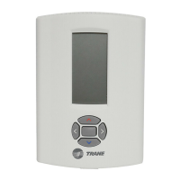
Pull out at the bottom of the thermostat first, then remove the top last.
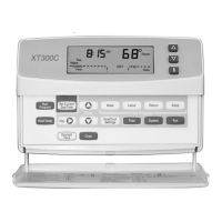
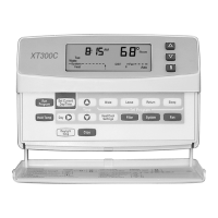
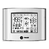
Explanation of keys for setting time, programs, overrides, installer setup, and system/fan operation.
Press keys with fingertip or blunt tool; sharp instruments can damage the keyboard.
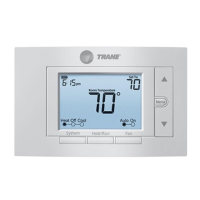
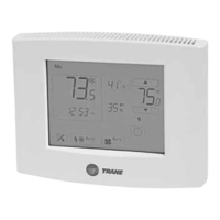
Setting system to Heat, Off, Cool, or Auto; setting fan to On or Auto for program periods.
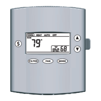
Location of the System key and how system selections (Heat, Off, Cool, Auto) are displayed.
Location of the Fan key and how fan selections (On, Auto) are displayed.
Shows default Wake, Leave, Return, Sleep periods with Heat, Cool setpoints and Fan setting.
Instructions for clearing periods like daytime energy-savings period as per Owners Guide.
Customize thermostat for specific systems, including Comfort-R, temperature display, and system changeover.
Press and hold Information, Increase, and Decrease keys to enter setup and change settings.
Visual representation of all segments on the thermostat's LCD display.
Shows how Installer Setup numbers and their corresponding options are displayed.
Lists setup numbers, descriptions, factory settings, and other choices for configuring the thermostat.
Allows changing between 7-day and 24-hour programming or disabling programming.
Configures fan control in heat mode: thermostat-controlled or conventional.
Sets number of heating stages and cycle rates for stage 1 and stage 2.
Sets number of cooling stages and cycle rates for stage 1 and stage 2.
Configures system changeover: Auto changeover or Manual changeover.
Activates adaptive recovery control for programmed start times.
Sets temperature display to F/C and clock format to 12-hour or 24-hour.
Configures fan operation duration after heating or cooling call ends.
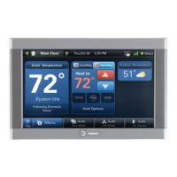
Enables outdoor temperature display and Comfort-R terminals.
Sets minimum deadband and minimum on-time for compressor during heat calls.
Sets minimum on/off times for compressor and cooling droop.
Sets temperature range stops for heating/cooling and display adjustment.
Sets programming to 7-day, 24-hour, or no programming.
Press Set Current Day/Time to begin the setting process.
On initial power up or after power loss, 1:00 PM flashes until a key is pressed.
Use Day and Time keys to set the current day and time accurately.
Press Run Program to exit the setting mode and save changes.
Press and hold Increase and Decrease keys to view all segments and test number 10.
Lists available self-tests: Heating, Cooling, Fan, Comfort-R, Keyboard, Device Information.
Press Time or Time V then Run Program to exit the self-test mode.
Details key presses for each self-test number, including Heating, Cooling, Fan, Comfort-R, Keyboard.
Tests heating equipment by turning on first and second stage heat.
Tests cooling equipment by turning on first and second stage cool and fan.
Tests fan operation by turning the fan on and off.
Tests Comfort-R terminals by reading HH terminals for humidity display.
Tests all keyboard functions by cycling through test numbers for each key.
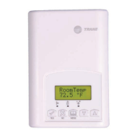
Press Temp ▲ and keys simultaneously, then Time to access thermostat information.
Shows the production date code in a 3-digit format (Month, last digit of Year).
Displays the software identification code of the thermostat.
Displays the software revision number of the thermostat.
Displays the model identification number of the thermostat.
Expose outdoor sensor to air for 5 minutes before reading temperature.
Covers display not on, incorrect temperature, dashes, and settings not changing.
Covers heating not coming on, or coming on momentarily and shutting off.
Covers cooling not coming on, or coming on momentarily and shutting off.
Covers no air from registers, filter indicator flashing, outdoor temp issues.
Covers internal memory failure causing time to display as EEE.
| Type | Non-programmable |
|---|---|
| Stages | 1 Heat/1 Cool |
| Temperature Range | 45°F to 90°F |
| Hold Function | Yes |
| Filter Change Alert | No |
| Power Source | 24V AC |
| Display | LCD |
| Backup Power | No |
| Warranty | 1 year |
| Programmability | No |