EasyManua.ls Logo

Trane XR401 - User Manual

Trane XR401
8 pages
Print Icon
To Next Page IconTo Next Page
Loading...
Installer’s Guide
XR401
ALL phases of this installation must comply with NATIONAL, STATE AND LOCAL CODES
TCONT401AN21MA
2 Heat (Gas, Oil* or Elec) / 1 Cool / Heat Pump
(Factory set for 2H/1C gas applications)
Electronic Non-Programmable
3 - 9 Wire Hookup (2 for outdoor sensor)
Fan Mode
Filter/OD
$
Introduction
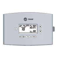
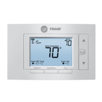
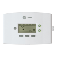
TCONT401AN21MA is a digital non-programmable 2Heat/1
Cool/Heat Pump/Heat-Cool wall mounted low voltage
(24VAC) Comfort Control with backlit LCD and keypad. It
maintains room temperature by controlling the operation of
heating, cooling and heat pump systems. The Comfort
Control is easily configured for heat pump or cooling only and
gas or electric heat applications via the user friendly In-
staller Setup menu. The Comfort Control features include
separate heating and cooling setpoints, selectable auto or
manual changeover, adjustable energy saving mode, adjust-
able filter reminder, outdoor temperature sensing, LitePort
technology for extended system diagnostics and fault notifica-
tion. Setup selections and diagnostics are stored indefinitely
in the Comfort Controls nonvolatile memory eliminating the
need for battery backup.
Safety Considerations
Read the following manufacturer instructions carefully.
Follow all local codes during installation. All wiring must
conform to local and national electrical codes. Improper
wiring or installation may damage comfort control.
Recognize safety information. This is the safety alert symbol
!
. When you see this symbol on the equipment and in the
instruction manual, be alert to the potential for personal
injury.
Understand the signal words DANGER, WARNING and
CAUTION. These words are used with the safety-alert
symbol. DANGER identifies the most serious hazards which
will result in severe personal injury or death. WARNING
signifies a hazard which could result in personal injury or
death. CAUTION is used to identify unsafe practices which
could result in minor personal injury or product and prop-
erty damage.
Note: Read the entire instruction manual before starting the
installation.
Application FIG
Heat Pump or A/C
1 Stage Heat Pump**, 1 Stage Aux Heat. Fig. 5
1 Stage Heat Pump**, 0 Stage Aux Heat. Fig. 5
1 Stage Cool, 2 Stage Heat (Gas, Electric or Oil*). Fig. 3
1 Stage Cool, 1 Stage Heat (Gas, Electric or Oil*). Fig. 4
1 Stage Cool, 0 Stage Heat. Fig. 4
0 Stage Cool, 2 Stage Heat (Gas, Electric or Oil*). Fig. 3
0 Stage Cool, 1 Stage Heat (Gas, Electric or Oil*). Fig. 4
* Requires external relay for oil furnace applications.
** External TAYPLUS103A required for dual fuel applica-
tions.
BAYSEN01ATEMPA required for outdoor temperature
sensing and display
SYSTEM MODE: Heat, Cool, Auto, Emergency Heat and Off
FAN MODE: Auto or On
Product Specifications
- Power Source: 20-30VAC, Class II, 50/60Hz.
- Cooling setpoint temperature range: 65F - 90F,
18.0C - 33.0C, 1F and 0.5C resolution.
- Heating setpoint temperature range: 40F- 85F,
5.0C - 30.0C, 1F and 0.5C resolution.
- Default set points: 68F, 20.0C Heat, 78F, 25.5C Cool
- Storage Range: -40F to 140F, 5% - 90% RH non-
condensing.
- Operating Temperature range: 32F - 110F, 5 - 90% RH
non-condensing.
- Outdoor Temperature Display Range: -40F - 140F.
- Minimum Cycle Off Time Delay: Cooling - 5 minutes,
Heating - 1 minute.
- Use minimum 18 gauge NEC approved control
wiring.
Contents
Introduction ........................................................................ 1
Application.......................................................................... 1
Product Specifications ...................................................... 1
Installation .......................................................................... 2
Mounting and Wiring .......................................................... 2
SETUP ................................................................................. 3
Checkout ............................................................................. 4
Troubleshooting ................................................................. 6
Features .............................................................................. 7
18-HD29D2-4

Questions and Answers

  • T
    Tiffany JohnsonSep 4, 2025
    What does it mean when the service indicator is flashing on my Trane Control Panel?
    • T
      Terry RamirezSep 4, 2025
      A flashing service indicator on your Trane Control Panel suggests a control EEPROM write error. Press any key and check/re-enter setup choices.
  • J
    justin02Sep 18, 2025
    What causes a heating cycle to be too fast or slow on a Trane Control Panel?
    • D
      David Holt MDSep 18, 2025
      A heating cycle that's too fast or slow on your Trane Control Panel is likely due to the control's placement or the heating system's size. Verify cycle rate adjustment using Step 27.
  • E
    Eugene WallsSep 16, 2025
    Why is the cooling cycle too fast or slow on my Trane Control Panel?
    • J
      James MendezSep 16, 2025
      If the cooling cycle is too fast or slow on your Trane Control Panel, it's likely influenced by the control's location or the cooling system's size. Verify cycle rate adjustment using Step 19.
  • B
    barrjenniferSep 14, 2025
    What to check if the fan doesn't operate properly in heat or cool mode on Trane Control Panel?
    • K
      Kathy HicksSep 14, 2025
      If the fan isn't operating correctly in heat or cool mode on your Trane Control Panel, it could be due to incorrect wiring or inoperative heating/cooling equipment. Correct the wiring. Repair the system.
  • S
    stephaniereidSep 12, 2025
    Why can't I set the heating setpoint above 80 degrees on my Trane XR401 Control Panel?
    • J
      James WarrenSep 12, 2025
      If you cannot set the heating setpoint above 80 degrees on your Trane Control Panel, the deadband between Heating and Cooling is set too high. Decrease the Deadband setting using User Setup Step 42.
  • K
    Karen BarkerSep 12, 2025
    What does it mean when the service indicator is solid and temperature display is '--' on my Trane Control Panel?
    • Y
      ywhiteSep 12, 2025
      If the service indicator is solid and the temperature display shows '--' on your Trane Control Panel, it indicates that the indoor temperature sensor is open or shorted. Replace the Control.
  • P
    patriciacunninghamSep 9, 2025
    Why does the room temperature overshoot when using the Energy Savings Key on my Trane XR401 Control Panel?
    • D
      David MullenSep 9, 2025
      Room temperature overshoot when using the Energy Savings Key on your Trane Control Panel, or when the Heat/Cool settings are changed more than 2 degrees, is caused by oversized heating or cooling equipment. The control cannot respond fast enough to prevent overshooting. Set the Control Response rate to "Fast" using Step 33.
  • M
    Mark PollardSep 7, 2025
    How do I fix an incorrect outdoor temperature display on my Trane XR401?
    • B
      Benjamin WilsonSep 7, 2025
      To correct an incorrect outdoor temperature display on your Trane Control Panel, first calibrate the sensor using User Setup Step 50. If the issue persists, disconnect the outdoor sensor from the controls terminal block and check the sensor and field wiring resistance value using Table 2.
  • A
    Albert MorrowSep 5, 2025
    How to calibrate the indoor temperature display on a Trane XR401?
    • K
      Keith KingSep 5, 2025
      If the indoor temperature display on your Trane Control Panel is incorrect, it means the temperature display needs calibration. Calibrate the sensor using User Setup Step 49.
  • K
    Kimberly MorrowAug 21, 2025
    How to fix a Trane XR401 Control Panel when the display won't come on?
    • A
      Alexa MossAug 21, 2025
      If the Trane Control Panel display doesn't come on, the possible causes are a blown fuse or tripped circuit breaker, the furnace power switch being OFF, or the furnace blower compartment door/panel being loose. To resolve this, replace the fuse or reset the breaker, turn the switch to ON, or replace the door panel in the proper position to engage the safety interlock or door switch.

Summary

Introduction

Application Overview

Describes the HVAC system configurations supported by the thermostat.

Product Specifications

Lists technical details like power source, temperature ranges, and dimensions.

Installation Guide

Location Selection

Provides guidelines for mounting the thermostat and outdoor sensor.

Setup Procedures

Installer and User Setup

Explains how to enter and configure installer and user setup menus.

Control Configuration

Installer Setup Options (ISU)

Details specific installer setup parameters and choices.

User Setup Options (USU)

Details specific user setup parameters and choices.

Troubleshooting Common Issues

Trane XR401 Specifications

General IconGeneral
BrandTrane
ModelXR401
CategoryControl Panel
LanguageEnglish

Related product manuals