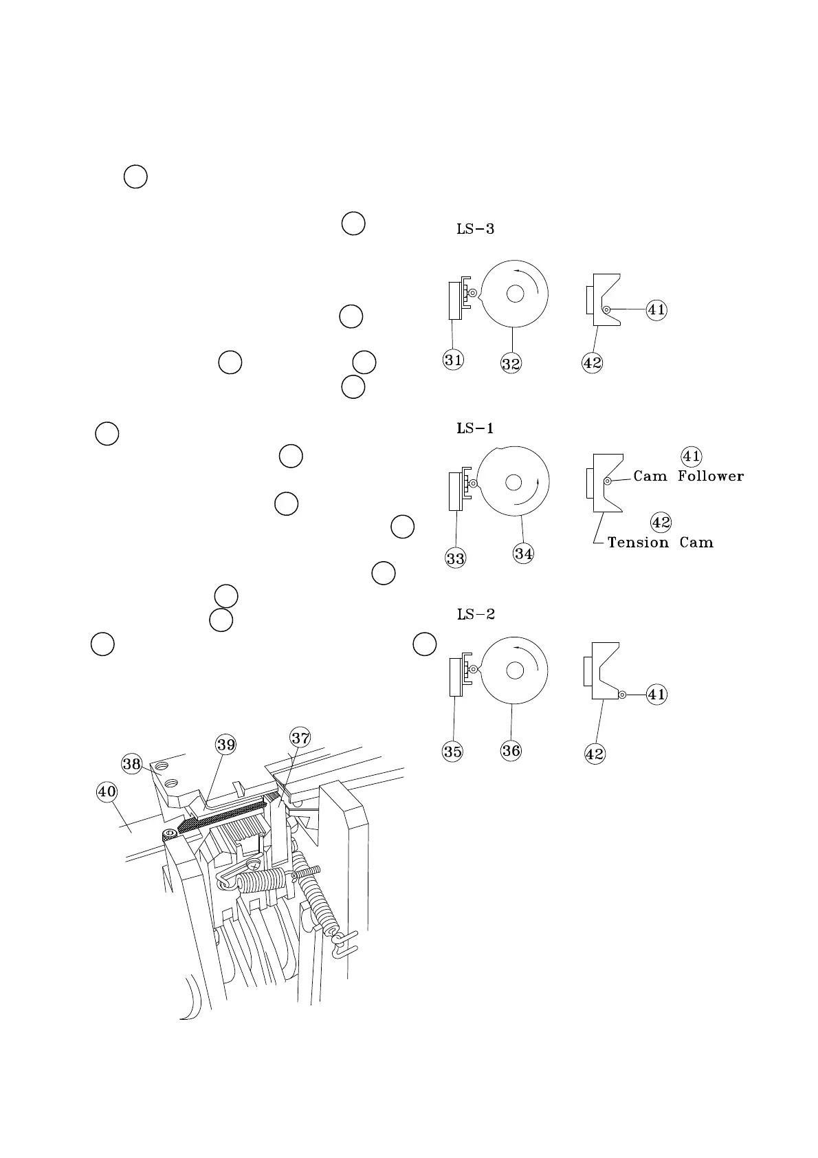
adjusted by Limit Switch Contactor, 32 .
to stop at home position and is
LS3, 31 controls the machine
the control unit, the right Press Unit 37
stops and the strap starts reversing. In
When LS1 is activated, the control unit
backward and LH Strap Guide Flap, 40 , opens
under Slide Table, 38 . Strap Guide, 39 moves
rises up to the top and grips the strap
shows the correct position of control unit with
rising on the Tension Cam, 42 . The illustration
, 41 stays at its position before it starts
completely. At this moment, cam follower
correct adjustment of LS1, 33 .
LS1 is adjusted by Limit Switch Contactor, 34 .
The strap feed cycle is triggered by LS2, 35
To activated LS2, 35 , correctly, adjust limit
switch contactor, 36 , so that the cam follower,
41 , strats descending along the tension cam, 42 .
-13-
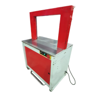
Limit switches ( Movements of control unit)