ENGLISH
31
www.trapp.com.br
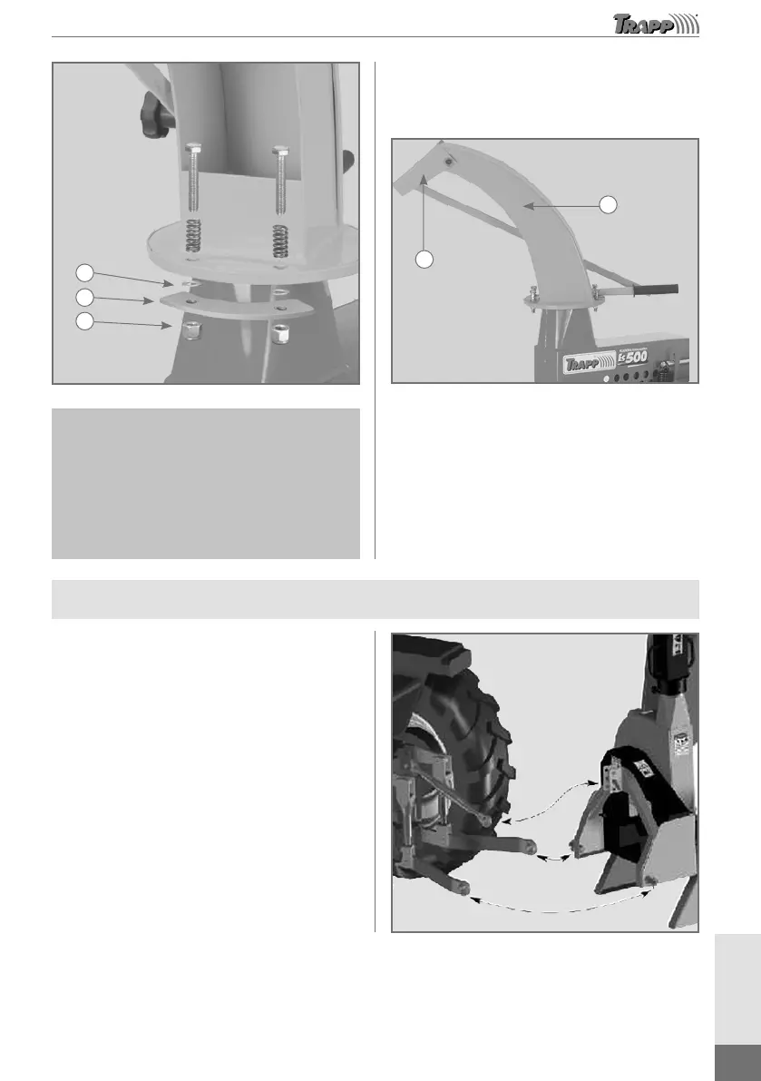
A
B
C
Image merely
illustrative
Figure 3
Note: The holders are secured on the ration
outlet device only; the holes on the machine
cover flange are not used.
Tighten the nuts in a way that the ration outlet
device can rotate when necessary. See figure
below for proper assembly of the ration outlet
device.
After assembling the spout (1), rotate it to check
if it is tight enough. Position the spout (1) and the
outlet device (2) in the desired operation direction,
as indicated in Figure 4.
Image merely
illustrative
1
2
Figure 4
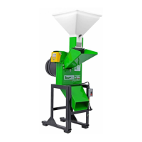
Cardan Shaft Assembly
Carefully read the Operator’s Manual, as well
as the tractor and cardan shaft manufacturer’s
instruction manuals. The ensiling machine was
manufactured to be coupled to a tractor equipped
with a hydraulic lift with 3 universal hitch points,
the set will already be assembled from the factory
for a cardan shaft with 6 splines, as shown in the
following illustration.
Image for illustrative purposes only