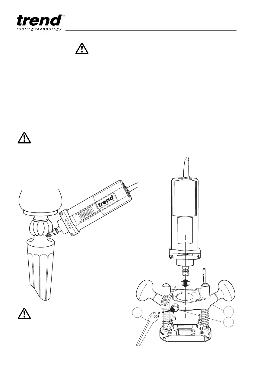
Removing the Router from the Plunge
Base
■ Never separate the router from the base while
a cutter is fitted in the collet. Always
disconnect the router from the power supply
before separating the router from the base.
■ Use the 15mm open ended spanner (1) to
release the clamping nut (2) on the base.
Slacken the nut off until the motor unit slides
out of the base (3).
■ When re-fitting the motor unit, ensure that the
switch is facing the front of the router so that
it is accessible when plunge routing.
■ Ensure that the clamping nut is re-tightened
before using the router for normal plunge
cutting operations.
Carving and Grinding
Carving and grinding applications can be carried
out with the router removed from its plunge
base. When using the router in this way, only
use multi flute carving, engraving, or de-burring
rasps and burrs.
The mounting boss on the T3 router has a
diameter of 42mm. To allow the router motor
unit to be mounted in a drill stand for overhead
routing applications a 42mm to 43mm collar is
required, Ref. T3/COLLAR.
Always unplug the machine
from the power supply before
separating the router from its
plunge base.
Never use high speed router
cutters for carving operations.