-7-
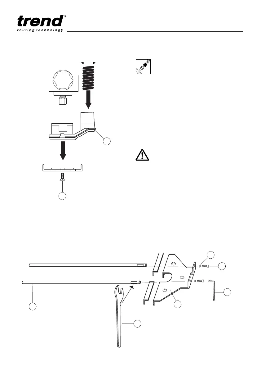
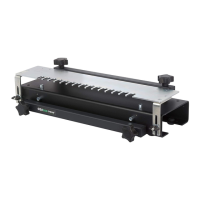
Fitting and Removing the
Dust Extractor Spout
■ Insert the extractor spout (1) into the base of
the router.
■ Fit the two countersunk headed screws (2)
from beneath and screw-on into the
captivated nuts in the spout.
■ Dismantle in reverse order.
■ The extractor spout is suitable for dust
extractors with a hose diameter of 35mm.
T3
ASSEMBLY & ADJUSTMENT
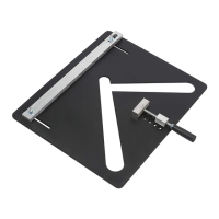
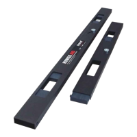
Fence Assembly
■ Fit the spring washers (1) over the socket
head screw (2) and pass the screw through
the fence (3).
■ Screw the side fence rod (4) onto the screw
and tighten by hand.
■ Use the cut-out in the side of the 17mm
spanner (5) to hold the flat on the rod while
tightening the screw with the hex key (6).
■ Repeat for other rod assembly.
Whenever possible use the
dust extraction spout with a
suitable extractor when
routing.