MAIN COMPONENTS OF THE COLUMN
The handlebar components are identied as follows:
1. Upper support optional solution tank kit.
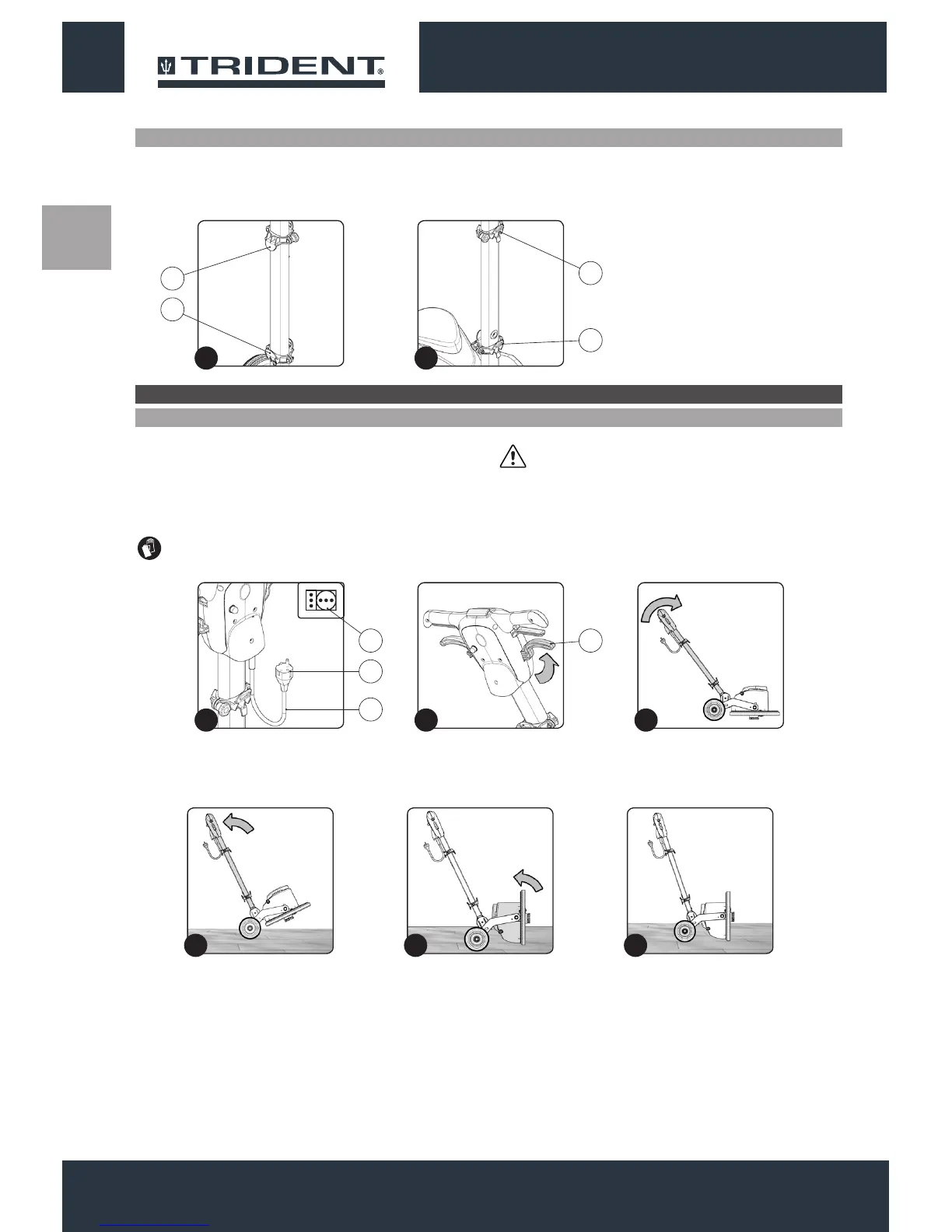
To insert the pad holder into the brush head body of the appliance,
proceed as follows:
1. Check that the plug (1) on the power cable (2) has been taken out
of the socket (3) of the mains supply(Fig.1), and if not, disconnect
it.
ATTENTION: You are advised to always wear protective
gloves, to avoid the risk of serious injury to your hands.
2. Lower support optional solution tank kit.
3. Upper cable tidy.
4. Lower cable tidy.
ATTENTION: To prevent damaging the power cable,
disconnect the plug from the mains socket by directly pulling
the plug and not the cable.
2. Check that the handlebar is in the vertical position, if not, press
the uncoupling lever (4) (Fig.2) and turn the handlebar to the
vertical position (Fig.3). When the handlebar is vertical, release
the uncoupling lever (4).
PREPARATION OF THE APPLIANCE
INSERTING THE PAD HOLDER
3. Lightly tip the machine back (Fig.4), block one of the rear wheels
and shift the control column backwards.
4. Turn the brush head into the vertical position (Fig.5).
5. Bring the rotated brush head into contact with the oor (Fig.6).
1212
12
4
3
2
1
2
1
3 4
1
1 2 3
2
4 5 6