Do you have a question about the TRIMOS V3 and is the answer not in the manual?
General safety instructions and disclaimer for proper user manipulation of the instrument.
Explanation of safety symbols used throughout the manual to indicate potential hazards.
Covers electrostatic discharge, prohibition of disassembly, and environmental operation guidelines.
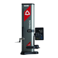
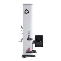
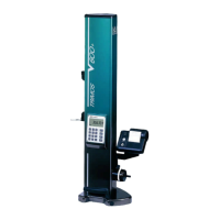
Identification and description of the physical parts of the TRIMOS measuring instrument.
Details on the instrument's data ports, power connections, and probe interfaces.
Explanation of the instrument's display elements, status symbols, and screen lines.
Lists all items included in the standard packaging of the measuring instrument.
Step-by-step guide for unpacking, cleaning, and assembling the instrument.
Describes manual and motorized carriage movement operations for the instrument.
Guides through initial power-on, reference setting, and probe constant input.
Selection process for height, diameter, and centerline measurement modes.
Procedures for performing vertical measurements and chain dimensions.
Instructions for measuring internal/external diameters and centerlines.
Setting measurement origins and assigning preset values.
Adjusting the display resolution for measurement accuracy.
Setting, memorizing, and manually recording the probe constant.
Switching between metric (mm) and imperial (inch) units.
Performing measurements to find minimum, maximum, or difference values.
Calculating averages and differences between recorded measurements.
Resetting the display to zero for various measurement contexts.
Procedures to measure the perpendicularity of a surface using different methods.
Accessing, navigating, and processing stored measurement data.
Measuring distances and centerlines between features.
Reversing measurement direction for expanded range.
Procedure for switching probe holders while maintaining measurement origin.
Manually inputting the probe constant value.
Configuring display formats for height measurements (standard/direct).
Applying a factor to adjust measurements for material expansion/contraction.
Compensating measurements for ambient temperature variations.
Connecting the instrument to a PC via USB for data transfer.
Connecting the instrument via RS232 for data transfer.
Specifies prerequisites for executing remote control commands.
Reference for ASCII commands for remote instrument operation.
Adjusting the balancing of the floating probe suspension.
Electronically setting the force applied by the measuring probe.
Setting the number of available measurement references (1-9).
Adjusting air cushion airflow for instrument displacement.
Adjusting probing sensitivity based on insert type for accuracy.
Enabling/disabling automatic reversal point detection for diameter measurements.
Configuring data output for diameter and centerline measurements.
Selecting between manual and automatic data transfer methods.
Masking or activating the second display line in height mode.
Assigning specific functions to programmable buttons on the instrument.
Locking or unlocking the measurement unit to prevent changes.
Entering the height of a non-standard reference gauge for calibration.
Setting the time interval before the instrument enters standby mode.
Adjusting the frequency and volume of the instrument's buzzer.
Choosing the function active immediately after instrument start-up.
Displaying instrument serial number and firmware versions.
Viewing the latest calibration date and entering the next calibration date.
Understanding probing indicators, direction, and acoustic signals for precise measurements.
Adjusting probe suspension to ensure consistent measuring force.
Utilizing keyboard keys or function buttons for motorized carriage movement.
Step-by-step guide for replacing the instrument's battery block.
Environmental guidelines for recycling electronic components (WEEE).
Procedure to force a reset of the instrument's electronics in case of blocking.
Guidance on cleaning instrument parts and air cushion pads.
Information on contacting local agents for service and repairs.
How to find an official list of TRIMOS agents.
Technical drawings and specific dimensions for V3, V4, V5, and V6 models.
Technical drawings and specific dimensions for the V8 model.
Detailed technical specifications for the V3 instrument.
Detailed technical specifications for the V4 instrument.
Detailed technical specifications for the V5 instrument.
Detailed technical specifications for the V6 instrument.
Detailed technical specifications for the V8 instrument.
| Brand | TRIMOS |
|---|---|
| Model | V3 |
| Category | Measuring Instruments |
| Language | English |