Do you have a question about the TRIMOS V9 and is the answer not in the manual?
General guidance on reading and following manual instructions for safe operation.
Explanation of symbols used in the manual to indicate hazards and warnings.
Critical safety advice regarding electrostatic discharge, environmental conditions, and instrument handling.
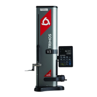
Identification and description of the main components and interfaces of the V7 model.
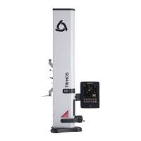
Identification and description of the main components and interfaces of the V9 model.
Details of items included in the instrument's standard packaging for initial setup.
Step-by-step guide for preparing and connecting the instrument for use.
Instructions for powering on the instrument and performing the initial startup sequence.
Explanation of how to use manual and motorized carriage displacement modes.
Procedure for setting the reference point and measuring the probe constant.
Overview of different display modes, including measurement history and graphic help.
Description of the static and scrolling function menu lines and their usage.
How to perform height measurements downwards, upwards, and chain dimensions.
Procedures for measuring internal and external diameters and centerlines.
Using modes to determine minimum, maximum, and difference values of measured surfaces.
How to set the display to zero for various measurement modes.
Managing references and preset values for simultaneous or conditional measurements.
How to select between metric (mm) and imperial (inch) units for measurements.
How to modify the display resolution for measurements.
Storing, deleting, and backing up measurement data in the buffer.
Recording and managing probe constants for accurate measurements.
Calculating and displaying differences between consecutive measurements.
Performing calculations on selected data points from the buffer.
Calculating the average of the two most recent measurements.
Measuring distances and centerlines between surfaces not related to diameters.
Measuring angles of sides or cones using specific accessories.
Programming and using tolerance limits to compare measurements against specifications.
Switching between standard and direct display modes for height measurements.
Procedure for changing the probe holder while maintaining the measurement origin.
Applying a shrinking or distending factor for specific measurement applications.
Inverting measurement direction to obtain positive values downwards.
Performing perpendicularity checks using a mechanical test indicator.
Using an electronic probe for detailed perpendicularity, inclination, and rectitude analysis.
Initial steps to begin 2D coordinate measurements and understanding the interface.
Steps for acquiring points along Z-axis and X-axis for 2D measurements.
Controls for zooming, panning, and selecting points within the 2D display.
Modifying the coordinate system, including translation and alignment.
Performing various measurements like angles, distances, and regression circles within 2D mode.
Managing data points by editing, adding construction points, or deleting them.
Exiting the 2-coordinate measurement mode.
Accessing the measurement sequence programming and execution menus.
Steps involved in creating and defining a new measurement sequence.
Loading and executing previously programmed measurement sequences.
Advanced programming options like assigning last probing value to next reference.
Exiting the measurement sequence programming and execution interface.
Accessing the menu for batch analysis and statistical evaluation.
Opening, analyzing, and interpreting batch data from measurement sequences.
Exiting the statistical analysis interface and returning to the main menu.
Description of available communication ports for data transfer and printing.
Settings for USB printer, serial printing, and data transfer parameters.
Procedure for transferring data to a PC using a USB B connection.
Methods for transferring data via RS232 to printers or PCs.
Steps for connecting and configuring a USB printer for output.
Settings for date, time, and screen brightness.
Settings for unit selection, setting gauge size, and angle measurement parameters.
Programming displacement handle buttons and measurement functions.
Settings for temperature units, air cushion, acoustic signal, and standby mode.
Settings for temperature compensation, instrument, and part temperatures.
Adjusting measuring force, probing sensitivity, and calibration dates.
Setting up the Smart Reverse function for efficient diameter measurements.
Adjusting the suspension balance for consistent measuring force.
Utilizing and adjusting the air cushion for smooth instrument displacement.
Activating and understanding the instrument's standby mode.
Procedure to reinitialize the instrument if it becomes blocked.
Guidelines for cleaning the instrument's parts and avoiding solvents.
Steps for replacing the main battery block when instrument autonomy is low.
Procedure for replacing the battery that maintains date and time.
Information on proper disposal and recycling of the instrument according to WEEE.
Contacting TRIMOS agents for problems, repairs, and transport advice.
Guidance on finding official TRIMOS agents via the website.
Detailed specifications for the TRIMOS V7 measuring instrument.
Detailed specifications for the TRIMOS V9 measuring instrument.
| Brand | TRIMOS |
|---|---|
| Model | V9 |
| Category | Measuring Instruments |
| Language | English |