User's Manual
750 50 0045 03 6
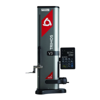
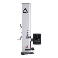
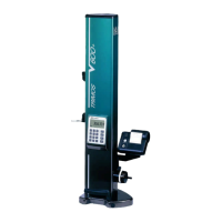
2.1 Instrument
1. Upper probe holder (V4 ÷ V6)
2. Screw for the adjustment of the floating probe suspension
3. Handle for carriage displacement
4. Transport safety screw for locking of probe suspension (chromium plated)
5. Lower probe holder
6. Insert holder (V3 ÷ V6)
7. Measuring insert
8. Operating handle for the displacement of the instrument
9. Button for activation of air cushion and programmable functions keys (V4 ÷ V6)
10. Base with air cushion system for instrument displacement (V4 ÷ V6)
11. Handwheel for carriage displacement / Activation of manual/motorised movement
(V5 ÷ V6)
12. Buttons for motorised displacement (V5 & V6)
2.2 Interfaces/Connectors
21. Mini USB connector (on top of display unit)
22. Connector for electronic perpendicularity probe (V6 & V8)
23. Connector for RS232 communication (on lower right side of height gauge)
24. AC adaptor connection (on lower right side of height gauge)
2.3 Display
31. Status symbols (battery level, units, active functions, etc.)
32. Upper display line
33. Lower display line
34. Visual signal of function activation
35. On/Off key (power ON / OFF)
36. Print-out of data
37. Function key: Selection of height and diameter - centerline measurements / Validation
key
38. Function buttons and numeric keypad.
39. Zero setting of the display