6.2 INSTALLATION METHOD
The PV modules must be installed in accordance with the installation instructions specified in this
user manual to comply with the IEC certification. Before installing, please read this section carefully
to familiarize yourself with the complete installation processes.
The modules and racking system can be connected through the mounting holes, clamps, or an
embedded system. Installation of modules must be carried out in accordance with the installation
requirements. If you wish to use a different installation method, please consult Trina Solar customer
service or technical support team. If in such case that an alternative mounting method is used but
not approved by Trina Solar, the module may get damaged and the warranty will be invalidated.
The mechanical loads described in this manual are the test loads. For calculating the equivalent
maximum design loads, a safety factor of 1.5 (Mechanical loads=Design loads×1.5 security
coefficient) needs to be considered in compliance with the requirements of the local laws and
regulations. The design loads are strongly related to the construction, applied standards, location
and local climate conditions; therefore, have to be determined by the racking suppliers and/or the
professional engineers. For detailed information, please follow local structural code or contact your
professional structural engineer.
The modules shall be mounted on continuous rails that extend beneath the modules. If modules are
mounted without continuous rails, the maximum allowable load will be reduced, which needs to be
re-evaluated by Trina Solar.
The minimum distance between two modules is 5 mm (0.2 inch). If using special trackers, the
minimum distance should be selected according to the technical requirements of the tracker
suppliers.
6.2.1 SCREW INSTALLATION
The frame of each module has 4-φ9*14mm mounting holes, that are ideally placed to optimize the
loading capacity to secure the modules on the supporting structure.
To maximize mounting longevity, Trina Solar strongly recommends the use of corrosion proof
(stainless steel) fixings.
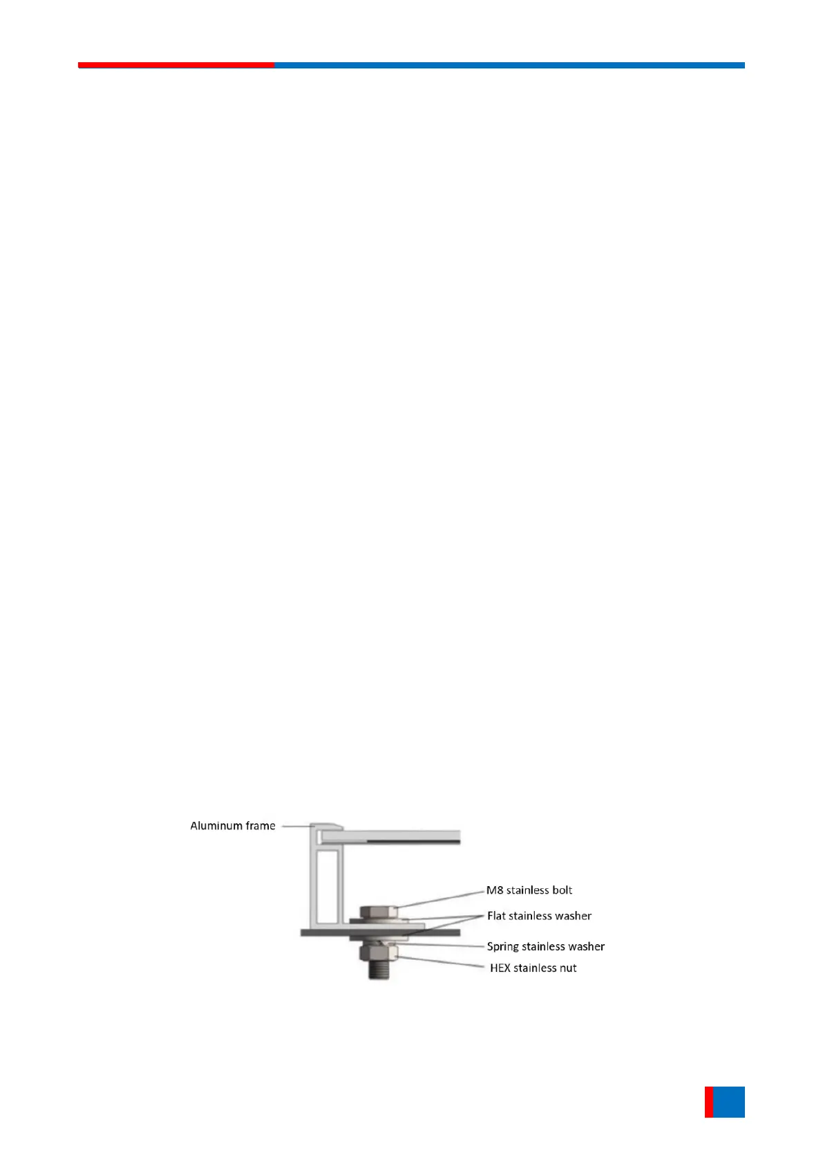
Secure the module in each fixing location with one M8 bolt, two flat washers, one spring washer and
one nut (see Figure 1) and tighten them to a torque of 16-20 N.m (140-180 lbf.in.). The yield strength
of bolt and nut should not be less than 450 MPa.
Figure 1. PV module installed with bolt fitting method.