6.2.2 CLAMP INSTALLATION
Trina Solar has tested its modules with a number of clamps from different manufacturers, it is
recommended to use fixing bolt of at least M8. The clamp shall not be malfunctioned due to
deformation or corrosion during the loading process. It is recommended to use a clamp with length
of ≥50 mm (1.97 inch) and thickness of ≥4 mm (0.16 inch), aluminum alloy 6005-T6, Rp0.2 ≥ 225
MPa,Rm ≥ 265 MPa.
The clamp must overlap the module frame by at least 8 mm (0.32 inch) but not more than 12 mm
(0.47 inch).
Modules clamps should not come into contact with the front glass and must not be deformed.
Please make sure to avoid shading effects from the module clamps.
The module frame shall not to be modified under any circumstances.
The clamps shall not to be out the edge of the module under any circumstances.
When choosing clamp installation method, use at least four clamps on each module, two clamps
should be attached on each long sides of the module (for portrait orientation). Depending on local
wind and snow loads, additional clamps may be required to ensure that modules can bear the extra
load.
Applied torque should refer to mechanical design standard according to the bolt customer is using,
for example: M8: 16-20 N.m (140-180 lbf.in)
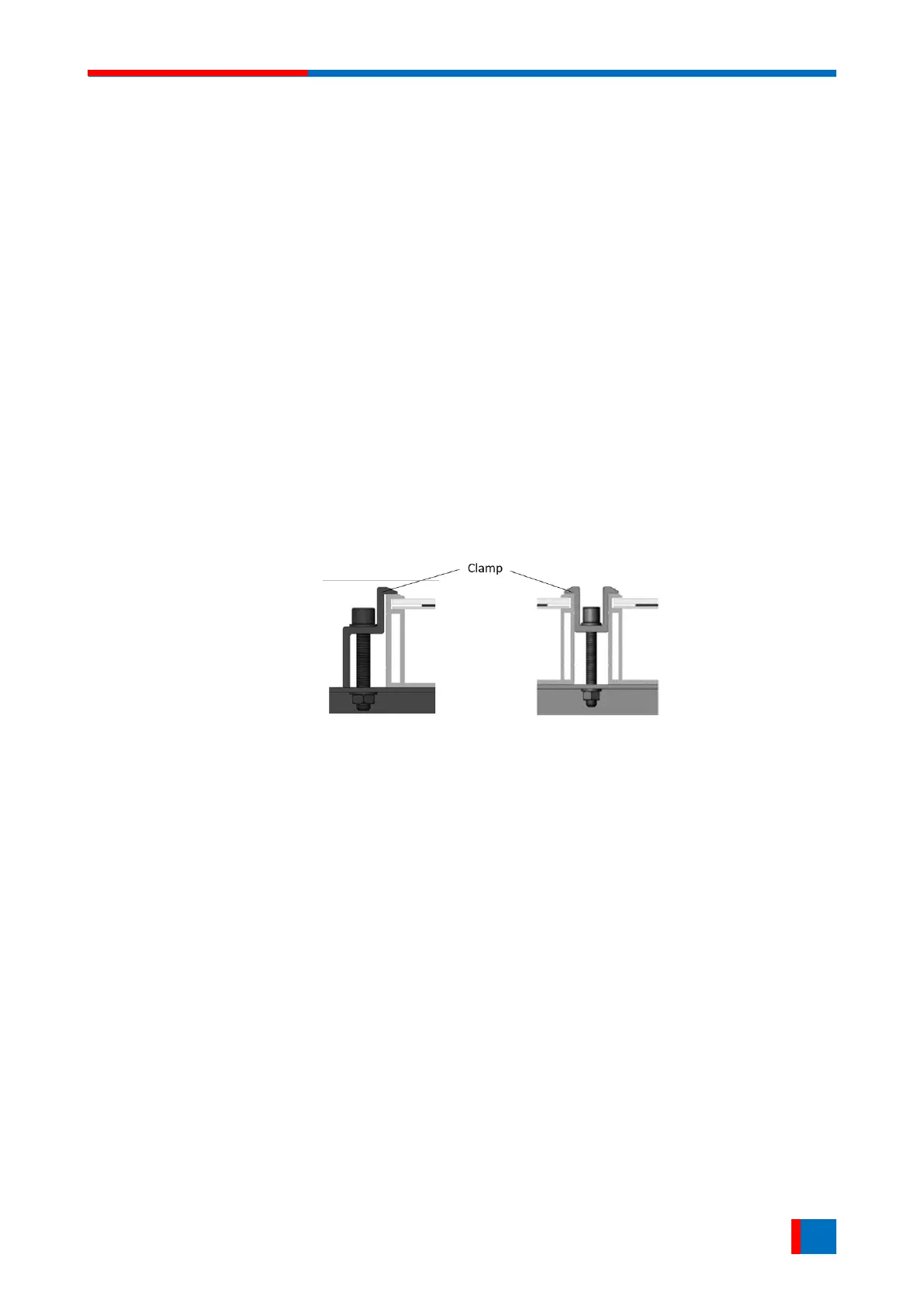
The installation method of clamps is shown in Figure 2.
End clamp installation Middle clamp installation.
Figure 2. PV module installed with clamp fitting method.
Clamp positions are of crucial importance for the reliability of the installation. The clamp centerlines
must only be positioned within the ranges indicated in table below, depending on the configurations
and loads.