6.2.3 SINGLE-AXIS INSTALLATION
The bolts used in this section is to secure the module in each fixing location with an M6 bolt, two flat
washers, a spring washer and a nut, and tighten them to a torque of 16-20 N.m (140-180 lbf.in.).
For Vertex series modules, all parts in contact with the frame should use flat stainless steel washers
of minimum 1.5 mm (0.06 inch) thickness with an outer diameter of 16-20 mm (0.63-0.79 inch),
except for DEG18MC.20(II) / DEG19C.20 / NEG19C.20 / DE21 using an outer diameter of 16-18
mm (0.63-0.71 inch).
Trina Solar modules can be used with trackers produced by different manufacturers, please check
Appendix A for details.
When using reinforced attachment I*, all accessories should be mounted together onto the troque
and the accessory bolts should be tightened using wrench tools, while the junction box should be
avoided when installing the attachment.
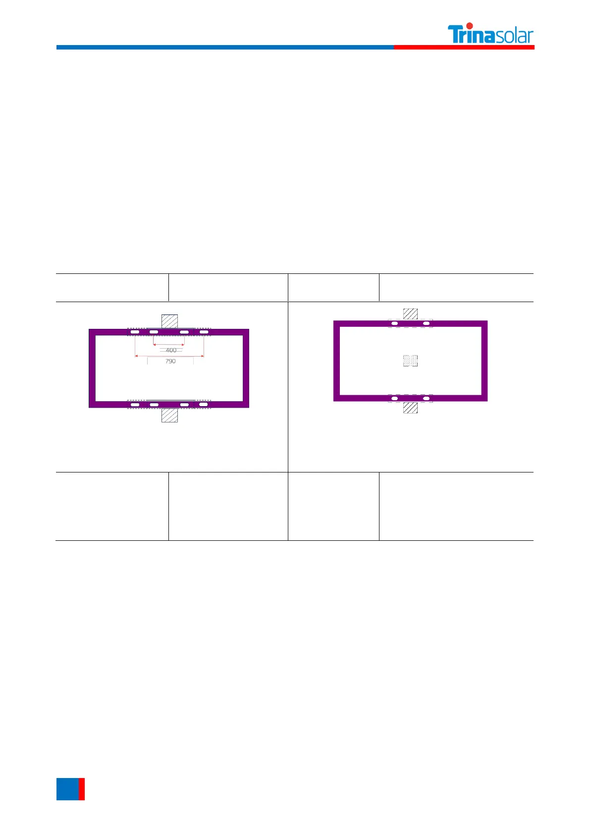
The module has to be installed on the purlins.
Mounting rails run perpendicular to the long side frame.
Distance between mounting holes is 400 mm/790mm.
This installation method is for the tracker with reinforced
attachment Ⅰ* only.
Mounting rails run perpendicular to the long side frame.
Distance between mounting holes is 400 mm.
DEG18MC.20(II)
DEG20C.20
NEG20C.20
DEG21C.20
NEG21C.20
Uplift load ≤ 2400 Pa
Downforce load ≤ 2400 Pa
Uplift load ≤ 2400 Pa
Downforce load ≤ 2400 Pa
*Reinforced attachment Ⅰ: bumper
If 790mm installation hole used for module installation, please refer to Appendix A: Trackers Compatibility
for the corresponding mechanical loads.
Please note that the mechanical loads for the above two single-axis installation methods are just
regular values, the mechanical loads may different with different trackers, please refer to Appendix
A: Trackers Compatibility for details.
6.3 GROUNDING
All module frames and mounting racks must be properly grounded in accordance with the electrical
design and construction specifications, procedures, regulations and other special grounding
requirements applicable to the installation sites.
Proper grounding can be achieved by connecting the module frame(s) and all metallic structural
components together by using a suitable grounding conductor. The grounding conductors or wires
may be copper, alloy, or any other materials that are in accordance with the local electrical design