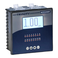
The ACCUVAR is a KVAR-based controller designed for Low Tension (LT) Capacitor Banks, functioning as a versatile meter and a robust electrical load management system. It is a microcontroller-based device that measures and calculates various electrical parameters, making it suitable for three-phase, four-wire electrical systems. The unit utilizes the three-watt-meter method to calculate KVA, KW, and KVAR.
Function Description:
The primary function of the ACCUVAR is to optimize power factor by controlling capacitor banks. It aims to maintain the power factor near unity, thereby contributing to electrical energy savings and optimal loading of distribution transformers. The controller also provides information on load imbalance, power factors at different times of the day, and peak loading hours, which are crucial for power usage planning and implementing automatic switched capacitor systems.
Important Technical Specifications:
The ACCUVAR operates on a three-phase and neutral 3P4W system.
- Voltage Input: Direct voltage input up to 300V L-N with a burden of 0.5VA.
- Current Input: Secondary current input of 5A or 1A. The CT ratio is site-selectable, with a reading range of 5-5000A. Burden is less than 1.0VA. Overload capacity is 6A RMS Continuous for 5A CT and 1.2A RMS Continuous for 1A CT.
- Power Supply: Self-powered from mains, with a wide operating voltage SMPS of 80 VAC - 480 VAC, 45-65 Hz.
- Relay Output: Max. 250 VAC switching voltage and Max. 1000W switching power. Expected mechanical life is >10 x 10^6 switching operations, and electrical life is >4 x 10^6 switching operations at a load of 200VA, Cos Ø = 0.5.
- Measurement Accuracy:
- Voltage (L-N: VRN, VYN, VBN): 0.5% of Reading.
- Current (Amps IR, IY, IB): 0.25% of Reading.
- Capacitor Current: 1.0% of Reading (CT Ratio Site Selectable).
- Line Frequency (45 to 65 Hz): 0.3% of Reading.
- Active Power (P): 1.0% of Reading (for IPFI>0.9).
- Reactive Power (Q): 1.5% of Reading (between 0.5 Lag to 0.8 Lead).
- Apparent Power (S): 1.0% of Reading.
- Power Factor: 1.0% of Reading (IPFI≥0.5), range 0.05 to 1.00 Lag/Lead.
- Total Active Energy (KWh): Range 0 to 9999999.9 KWh, accuracy 1.0S as per IS13779.
- Total Apparent Energy (KVAh): Range 0 to 9999999.9 KVAh, accuracy 1.0% of Reading.
- Total Reactive Energy (KVARh) (Lag & Lead): Range 0 to 9999999.9, accuracy 1.5% of Reading.
- Dimensions: Bezel 144 X 144 mm, Panel Cutout 138 X 138 mm, Depth of installation 55 mm.
- Operating Temperature: 10 °C to 50 °C.
- Weight: 0.82 Kgs (Approx.).
- Min. Operating Current: 1% or 5% of CT primary for FIFO/SFIFO Mode.
Usage Features:
The ACCUVAR features a 128 x 64 display and a user-friendly keypad for easy programming and operation.
- Main Features:
- 3P4W electrical system.
- Measurement of three powers (KW, KVA, KVAR), three-phase voltages (Vr, Vy & Vb), and currents (Ir, Iy, Ib).
- Auto phase sequence and polarity detection and correction.
- Active energy (KWh) and apparent energy (KVAh) measurement.
- Selectable Capacitor CT sensing (enable/disable).
- Selectable CT ratio for both load and capacitor current.
- Site-programmable PT ratio.
- Capacitor current (I cap) measurement.
- Phase-Wise PF, System PF, and Average integrated PF.
- Autosense/Manual types of KVAr control with capacitor bank size display for each stage.
- Eight/twelve/fifteen stage relays controller with one selectable alarm.
- Measurement of up to 15th Odd Harmonics and Total Harmonic Distortion (THD) for each Voltage and Current.
- Operational Modes:
- Run Mode: Displays various calculated parameters on different pages. Users can navigate through displays using arrow keys. The display auto-scrolls by default but can be frozen/unfrozen using the ENTR key.
- Programming Mode: Accessed by pressing the "PROG RUN" key for about five seconds. This mode allows users to set various field-programmable parameters, including:
- CT Ratio for load current and capacitor current.
- PT Ratio.
- Mode of control action (FIFO, SFIFO, PID, or VAR).
- Desired PF setting (LAG or LEAD).
- Switching type (Thyristor or Contactor).
- Number of Capacitor bank stages (2 to 15).
- Meter Address (1 to 255) and Baud rate (9600 or 19200) for RS485 communication.
- Alarm Mode (PF, I_THD, V_THD, or NO), Alarm Limit, and Alarm Delay.
- Switching Delay and Damp Factor for control action sensitivity.
- Reference Bank number for auto phase input detection.
- Auto phase input sequence detection and manual phase input sequence setting.
- Minimum Bank setting (100% or 75%).
- Auto sense of capacitors.
- Minimum Operating current for FIFO and SFIFO mode (Sensitive/Normal).
- PF value to switch OFF banks (Offset_PF).
- Installation and Commissioning: Involves mounting the unit, connecting R-Y-B phases and neutral, connecting main CT wires (M1/L1, M2/L2, M3/L3), connecting capacitor CT wires (CM/CL), and then programming the unit parameters. An "Autosense" feature helps detect and display bank sizes. Phase sequence detection is also available, requiring a load current greater than zero.
Maintenance Features:
- Troubleshooting Guide: The manual provides a comprehensive troubleshooting guide to identify and resolve issues, categorizing faults into system configuration, implementation errors, and actual equipment faults.
- Relay Protection: Relays are protected by snubbers against fast voltage transients.
- System Considerations: Emphasizes correct R, Y, B voltage connections, voltage within 10% of specified value, and proper control circuit setup.
- Fault Detection:
- Dead Relay: Check voltage availability at terminals using a multi-meter.
- Incorrect Power Factor Indication: Check and correct wiring to R, Y, B voltage terminals.
- Power Factor Not Improving: Check CT location (must be on main Incomer) and health of capacitors (measure current in each lead).
- Power Factor Not Reaching Set Value: Check if total installed KVAR is too low or if capacitors are healthy.
- Contactors Latching Up: Check external Manual Control configuration and ensure 440 VAC coils are not used.
- PF Meter Always 1.0: Indicates inadequate current through the Relay.
- Repairs: Site repairs are not recommended; defective relays should be sent to the factory.
- Warranty: Trinity provides a one-year limited warranty against defects in workmanship and materials from the date of original purchase, applicable in India. The warranty covers repair or replacement of defective units but excludes damage from misuse, improper installation, non-Trinity products, or unauthorized service.