1-12 Introduction
System Building
Trio Motion Technology
System Building
The modules and boards may be mixed within the system rules:
1) Every system must start with one Motion Coordinator master unit as this contains
the processor and logic power supply for the system.
2) The MC224 master unit can house up to 4 daughter boards. The Euro 205x, Euro
209 and MC206X will accept a single daughter board. These can be of any type.
3) The MC224 can have up to 3 axis expander modules added to house up to 16
daughter boards. 4 being housed in the Master and 4 in each of the axis expand-
ers.
4) Up to 16 CAN-16 I/O and 4 CAN Analog Input modules can be connected to any
Motion Coordinator.
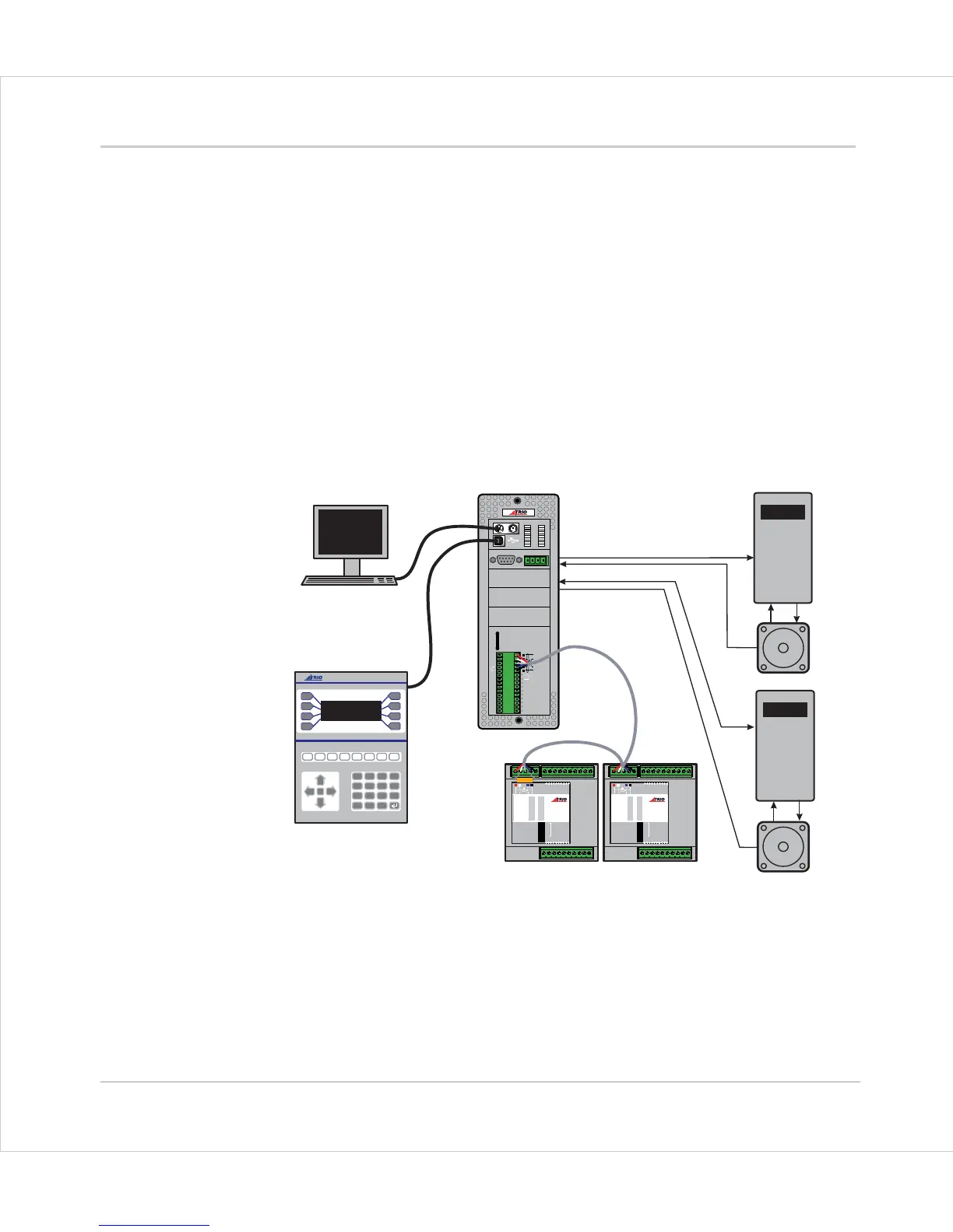
Typical System Configuration
ENCODER
V+ V- R
0v
8
9
10
11
12
13
14
15
0
OK
A
B
STA
1
2
3
4
5
6
7
SERIAL
BAT
5 4 3 2 1
9 8 7 6
MOTION
TECHNOLOGY
IO8
IO9
IO10
IO11
IO12
IO13
IO14
IO15
I 0
I 1
I 2
I 3
I 4
I 5
I 6
I 7
24v
0v
A1
A0
A-
B
0
1
2
3
4
5
6
7
8
9
10
11
12
13
14
15
1
2
4
8
16
32
OFF
MS NS
PR
DR
10 11 12 13 14 15 24v Ov98
7654 32100v 24v
NODE
ADDRESS
CAN16 -I/O
0
1
2
3
4
5
6
7
8
9
10
11
12
13
14
15
1
2
4
8
16
32
OFF
MS NS
PR
DR
10 11 12 13 14 15 24v Ov98
7654 32100v 24v
NODE
ADDRESS
CAN16 -I/O
7
4
1
-
8
5
2
0
9
6
3
.
Y
N
CLR
PC for Programming
Operator Interface
Motion Coordinator
CAN I/O
Servo Drive
Servo Drive
Motor
Motor
MOTION
TECHNOLOGY
MOTION
TECHNOLOGY
MOTION
TECHNOLOGY