Motion Coordinator Technical Reference Manual
Introduction 1-3
Trio Motion Technology’s range of Motion Coordinator products are designed to
enable the control of industrial machines with a minimum of external compo-
nents. The products may be combined to build a control system capable of driving
a multi-axis machine and its auxiliary equipment. The Motion Coordinator system
described in this manual allows you to control up to 24 servo or stepper motors,
Digital I/O and additional equipment such as keypads and displays from a single
master. Up to fifteen masters can be networked together using the Trio fibre optic
network allowing up to 360 axes of control. The controller is programmed using
the Trio BASIC programming language. This may be used to build stand-alone pro-
grams or commands can be sent from an external computer.
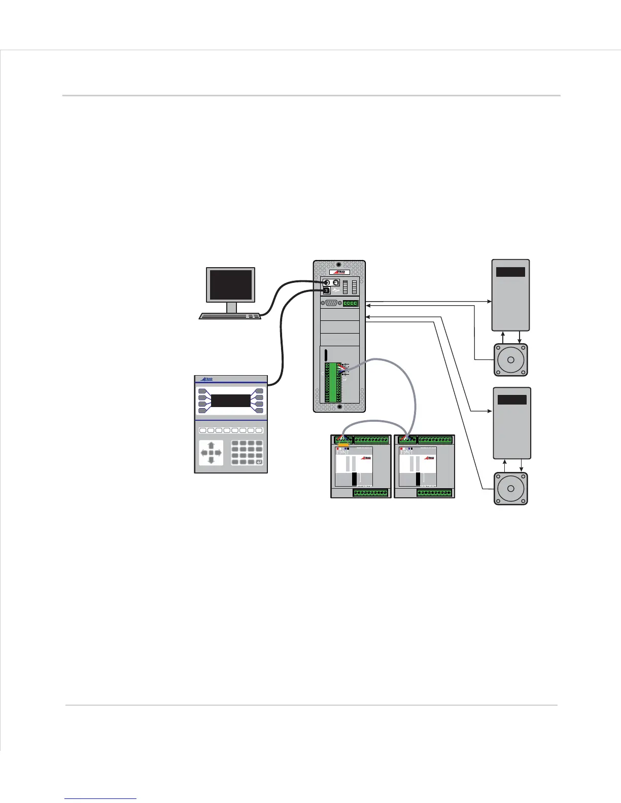
Typical System Configuration
The
Motion
Coordinator system is modular, allowing the user to tailor the controller
to their specific needs, but also allowing the flexibility to incorporate new modules if
needs should change.
ENCODER
V+ V- R
0v
8
9
10
11
12
13
14
15
0
OK
A
B
STA
1
2
3
4
5
6
7
SERIAL
BAT
5 4 3 2 1
9 8 7 6
MOTION
TECHNOLOGY
IO8
IO9
IO10
IO11
IO12
IO13
IO14
IO15
I 0
I 1
I 2
I 3
I 4
I 5
I 6
I 7
24v
0v
A1
A0
A-
B
0
1
2
3
4
5
6
7
8
9
10
11
12
13
14
15
1
2
4
8
16
32
OFF
MS NS
PR
DR
10 11 12 13 14 15 24v Ov98
7654 32100v 24v
NODE
ADDRESS
CAN16 -I/O
0
1
2
3
4
5
6
7
8
9
10
11
12
13
14
15
1
2
4
8
16
32
OFF
MS NS
PR
DR
10 11 12 13 14 15 24v Ov98
7654 32100v 24v
NODE
ADDRESS
CAN16 -I/O
7
4
1
-
8
5
2
0
9
6
3
.
Y
N
CLR
PC for Programming
Operator Interface
Motion Coordinator
CAN I/O
Servo Drive
Servo Drive
Motor
Motor
MOTION
TECHNOLOGY
MOTION
TECHNOLOGY
MOTION
TECHNOLOGY