Do you have a question about the Triplett CM200 and is the answer not in the manual?
Explains symbols indicating further manual consultation or potential hazards.
Provides essential operational precautions and storage guidelines for the meter.
Lists critical warnings about potential damage, shock, injury, and measurement hazards.
Details the maximum input values for various measurement functions.
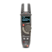
Identifies and labels all external components and ports of the meter.
Explains the meaning and function of various symbols shown on the meter's LCD display.
Instructions for performing AC current measurements using the open jaw clamp.
Steps for measuring AC and DC voltage using the meter.
Guide to using the Low Z function for detecting ghost voltages.
Procedure for measuring electrical resistance with the clamp meter.
Steps for performing continuity tests, including audible indication.
Instructions for measuring capacitance, including a warning about discharging capacitors.
How to test diodes and interpret the readings for functionality.
Guide for using the NCV function to detect live voltage without contact.
Details on using the MODE and Backlight buttons for function selection and illumination.
Explains how to activate and use the MAX/MIN measurement modes.
Instructions for freezing readings and activating the flashlight.
Information on the auto power off feature and how to disable it.
Guidelines for cleaning the meter and proper storage procedures.
Step-by-step instructions for replacing the meter's batteries.
Technical details for AC current and voltage measurements, including range and accuracy.
Details on resistance measurement ranges, resolutions, and accuracy.
Specific details for capacitance measurement, including ranges and accuracy.
Testing conditions and readings for Diode and Continuity functions.
Overall specifications like jaw opening, display type, and measurement rate.
Details on input impedance, AC response, and bandwidth.
Information on operating temperature, humidity, altitude, and battery type.
Safety certifications, overvoltage ratings, pollution degree, weight, and dimensions.
The Triplett CM200 200A True RMS AC Open Jaw Clamp meter is a versatile instrument designed for electrical measurements, offering a range of features for both professional and DIY use. This device is specifically engineered for measuring AC current without direct contact, enhancing safety and convenience. Its core function revolves around open jaw current measurement, allowing users to quickly and easily measure current by simply placing the clamp around a conductor, eliminating the need to break the circuit.
Beyond current measurement, the CM200 is equipped to handle various other electrical parameters. It supports AC/DC voltage testing, including a Low Z (Low Input Impedance) mode. This Low Z mode is particularly useful for identifying and eliminating "ghost voltages," which can often lead to inaccurate readings in non-powered wires running in close proximity to live AC voltage lines. By placing a load on the circuit, the Low Z setting dissipates these induced voltages, providing more reliable measurements. The meter also features resistance measurement, continuity testing with an audible signal, and capacitance measurement, making it a comprehensive tool for troubleshooting and verifying electrical circuits.
For safety and ease of use, the CM200 incorporates several practical features. It includes a Non-Contact Voltage (NCV) sensor with an indicator LED, which allows users to detect the presence of AC voltage without making physical contact with the conductor. This is a crucial safety feature, helping to identify live wires before any direct contact is made. The device also comes with a Data Hold function, enabling users to freeze the current reading on the LCD display for easier recording, especially in hard-to-reach areas or when the display is not immediately visible. A built-in flashlight is another thoughtful addition, providing illumination in dimly lit workspaces, further enhancing usability.
The CM200's display is designed for clarity and ease of interpretation. It features a Negative Polarity LCD Display, which ensures readings are clear and unambiguous. The display includes various icons to indicate the active measurement mode, such as alternating voltage and current, direct voltage and current, auto power off, auto range mode, continuity test, diode test, low battery, and units of measure. The MAX/MIN button allows users to capture and view the maximum and minimum values during a measurement session, which can be invaluable for monitoring fluctuating signals. The rotary function switch is backlit, along with the button and knob, ensuring visibility even in low-light conditions.
Operation of the CM200 is straightforward, guided by its intuitive rotary function switch and dedicated buttons. To measure AC current, users simply set the switch to the AC Current position and place the open jaw around the test lead. For voltage measurements, test leads are connected to the appropriate input jacks, and the meter automatically switches between AC or DC. Resistance, continuity, capacitance, and diode tests are similarly initiated by selecting the corresponding position on the rotary switch and using the MODE button to cycle through specific functions if needed. The NCV function works across all rotary switch positions, providing continuous safety monitoring.
The device is also designed with power conservation in mind. It includes an Auto Power OFF (APO) function, which automatically turns off the meter after approximately 15 minutes of inactivity, helping to extend battery life. This feature can be overridden by pressing and holding the MODE and Backlight Button during power-on, which is useful for extended measurement sessions.
Maintenance of the Triplett CM200 is minimal but essential for ensuring its longevity and accurate performance. Users are advised to periodically wipe the case with a damp cloth and mild detergent, avoiding abrasive cleaners or solvents. Before any maintenance or battery replacement, it is crucial to disconnect the meter from any circuit, remove the test leads, and turn off the device to prevent electrical shock. The battery compartment is easily accessible by removing a Phillips head screw, allowing for the replacement of the two 1.5V AA batteries. If the meter is to be stored for longer than 60 days, removing the battery is recommended to prevent leakage and potential damage. Operating the meter with an open case is explicitly warned against, emphasizing the importance of proper assembly for safety.
In summary, the Triplett CM200 is a robust and user-friendly open jaw clamp meter that combines essential electrical measurement capabilities with practical features like NCV detection, data hold, and a flashlight, all while prioritizing user safety and convenience. Its design and functionality make it a reliable tool for a wide range of electrical diagnostic tasks.
| Type | Clamp Meter |
|---|---|
| Continuity | Yes |
| Diode Test | Yes |
| Battery Type | 2 x AAA |
| Safety Rating | CAT III 600V |
| Display | LCD |
| DC Voltage Range | 600V |
| AC Voltage Range | 600V |
| DC Current Range | 600A |
| AC Current | 600A |
| Resistance Range | 60MΩ |
| Frequency Range | 10Hz to 1kHz |