User Manual
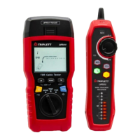
LVPRO10
TDR/Cable Tester
Contents
I. Overview 3
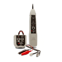
II. Accessories 3
III. Safety Information 4
IV. Features 4
V. Display Features (LVPRO10) 5
VI. Testing Mode 6
6.1 Testing Twisted-Pair Cabling 6
6.2 Testing Coaxial Cabling 12
VII.POE Mode 14
VIII.Tone Mode
15
8.1 Tone Mode Display 15
8.2 LVPRO10 Receiver -----------------------------------------------------------------------
16
IX. Calibrating Length Measurements (Only for test mode) ---------------------------- 18
9.1 Setting the NVP to a Specified Value ------------------------------------------------ 18
9.2 Determining a Cable’s Actual
NVP
---------------------------------------------------- 19
X. Backlight 19
XI. Unit of
Length
19
XII. Auto Power Off 19
XIII. Other functions 20
13.1 Low battery indication 20
13.2 Troubleshooting 20
13.3 Specifications 20
XIV. Maintenance 20