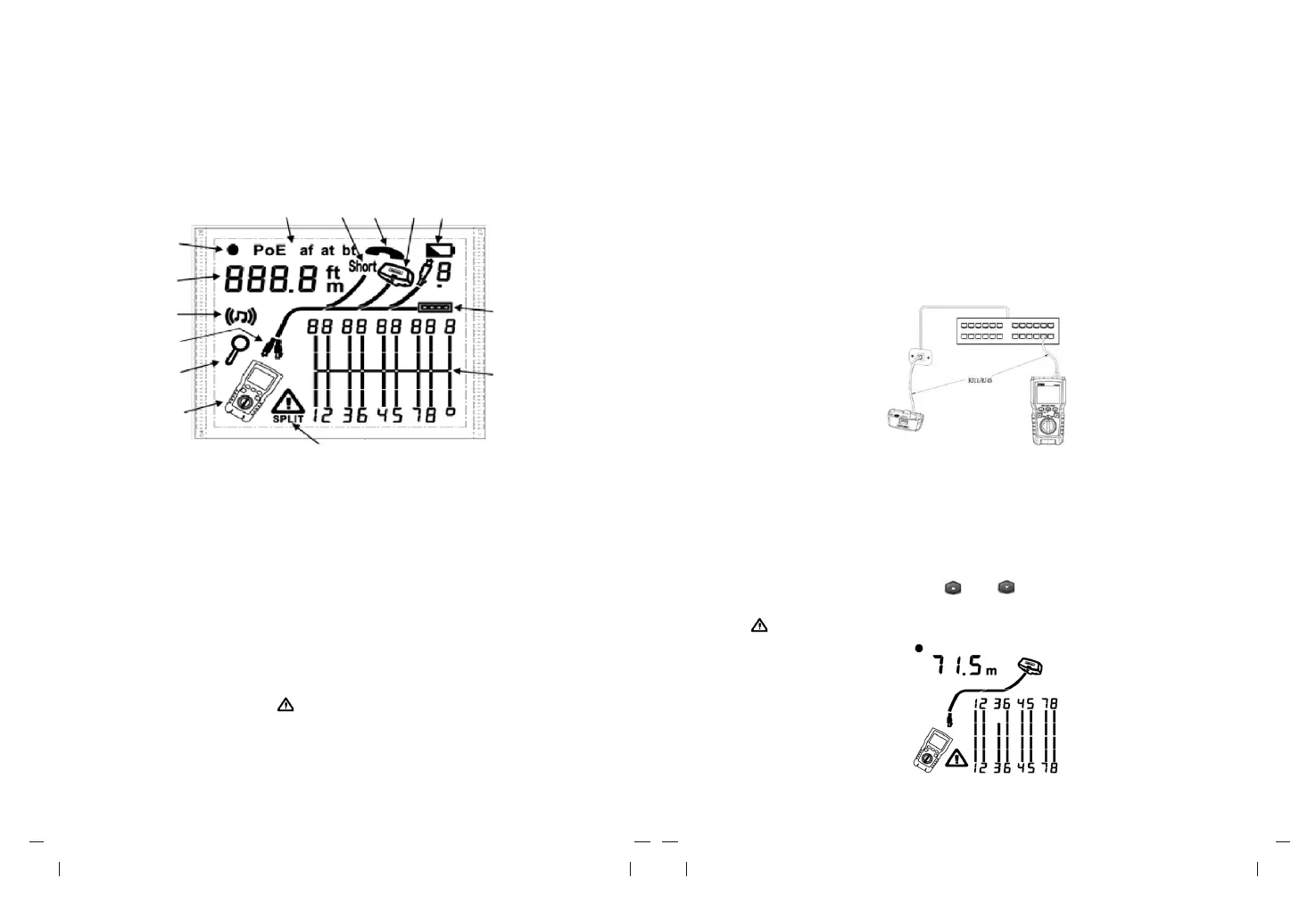
V. Display Features (LVPRO10 Main Unit)
7 8 9 10
11
6
5
4
12
3
2
13
1
14
1. Tester icon
2. Detail screen indicator
3. Indicates which port is active, the RJ45 port or the coaxial port.
4. Tone mode indicator
5. Numeric display with feet/meters indicator
6. Test mode indicator
7. POE mode indicator
8. Short circuit indicator
9. Telephone voltage indicator
10. Indicates a wire map adapter is connected to the far end of the cable
11.Low battery indicator
12.Ethernet port indicator
13.Wiremap diagram
14.Fault/high voltage indication: “ ” denotes fault or high voltage occurs at the cable.
SPLIT appears if split pair occurs.
VI. Testing Mode
6.1 Testing Twisted-Pair Cabling
6.1.1 Cabling Test
(1) Turn on the tester, and set the knob to "TEST", then press "PORT" to select RJ45
port.
(2) Connect tester and wire map adapter to the cabling, the test runs continuously until
you change modes or turn the tester off.
Note: Accurate cable length measurement without the need to connect a remote adapter,
however, an adapter is required for a complete wire map test.
Figure 6.1 Connecting to Twisted Pair Network cabling
6.1.2 Typical Testing Results
6.1.2.1 Open on Twisted Pair Cabling
As shown in figure 6.2, the third wire is open circuit, the three segments shown for the wire
pair length indicate the open is approximately 3/4 the distance to the end of the cabling.
The cable length is 71.5m.
To see the distance to the open, use “ ” and “ ” to view detailed results for the wire pair.
Note: If only one wire in a pair is open, both wires are shown as open. The warning icon
“ ” does not appear if both wires in a pair are open because open pairs are normal for
some cabling applications.
Figure 6.2 Open on Twisted Pair Cabling