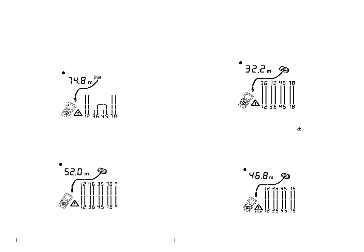
6.1.2.2 Short on Twisted Pair Cabling
Figure 6.3 shows a short between wires 5 and 6, the shorted wires flash to indicate the
fault.
The cable length is 74.8m.
Note: When there is a short, the far-end adapter and the mapping of the unshorted wires
are not shown.
Figure 6.3 Short on Twisted Pair Cabling
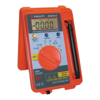
6.1.2.3 Crossed Wires
Figure 6.4 shows that wires 3 and 4 are crossed. The pin numbers flash to indicate the
fault.
length is 53m. The cable is shielded.
Note: Detection of crossed wires requires a far-end adapter.
Figure 6.4 Crossed Wires
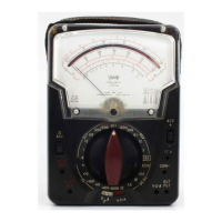
6.1.2.4 Crossed Pairs
Figure 6.5 shows that 1, 2 and 3, 6 are crossed. The pin numbers flash to indicate the fault.
Detection of crossed wires requires a far-end adapter.
Figure 6.5 Crossed Pairs
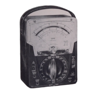
6.1.2.5 Split Pair
Figure 6.6 shows a split pair on 3, 6 and 4, 5. The symbol “ ” and split pair flash to
indicate the fault. The cable length is 46.8m.
In a split pair, continuity from end to end is correct, but is made with wires from different
pairs.
Split pairs cause excessive crosstalk that interferes with network operation.
Note: Cables with untwisted pairs, such as telephone cords, typically show split pairs
due to excessive crosstalk.
Figure 6.6 Split Pair