6
Operation
Installation
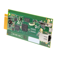
The MODBUSCARD should be installed in the accessory slot of a compatible SmartOnline UPS system.
Note: Prior to installing the card into the UPS, all configuration switches should be set to the values required by the UPS and your PC
communication ports.
1. Remove the screws securing the blank cover plate from the UPS and set them aside.
2. Detach the communication terminal connector from the MODBUSCARD.
3. Slide the configured MODBUSCARD into the UPS accessory slot
4. With the screws that were removed in step 1, attach the compatible cover plate that came with MODBUSCARD to the
accessory slot mounting points.
5. Re-insert the wired terminal strip connector into the MODBUSCARD port.
6. The MODBUSCARD’s red LED will flash to indicate the UPS is connected and ready for communication.
7. The user will need to supply the means of communication on the PC side via RS-232, RS-422, or RS-485, as well as the
appropriate monitoring software.
LED Indicators
LED Status Description
RED
OFF UPS disconnected
Flashing (1 second) UPS connected
GREEN Illuminated (0.2 seconds) Receiving PC request
Discrete Inputs (Range 0x0100 - 0x012F, Read Function 0x02)
The Read Discrete Inputs function code is used to read 1-2000 contiguous status of Discrete Inputs in a remote device. The
starting address and number of inputs is specified by the request Protocol Data Unit. Addresses start at 0 and Discrete Inputs
numbered 1-16 would address as 0-15.
Description Address Value 0 Value 1
Alarm Temperature 0x0100 OK Over Temperature
Alarm Input Bad 0x0101 OK Input Bad
Alarm Output Bad 0x0102 OK Output Bad
Alarm Overload 0x0103 OK Overload
Alarm Bypass Bad 0x0104 OK Bypass Bad
Alarm Output Off 0x0105 Output On Output Off
Alarm UPS Shutdown 0x0106 OK Shutdown
Alarm Charger Failure 0x0107 OK Charger Failure
Alarm System Off 0x0108 System On System Off
Alarm Fan Failure 0x0109 OK Fan Failure
Alarm Fuse Failure 0x010A OK Fuse Failure
Alarm General Fault 0x010B OK General Fault
Alarm Awaiting Power 0x010C OK Awaiting Power
Alarm Shutdown Pending 0x010D OK Shutdown Pending
Alarm Shutdown Imminent 0x010E OK Shutdown Imminent
Buzzer Status 0x010F Silence Alarm
Economy Mode 0x0110 No Yes
Alarm Inverter Bad 0x0111 OK Inverter Bad
Emergency Power Off 0x0112 Off On
Buzzer State 0x0113 Disable Enable
Battery Ground Fault 0x0114 OK Battery Ground Fault
Reserved 0x0115
Reserved 0x0116