7
Feature Identification
C
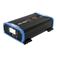
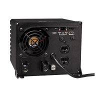
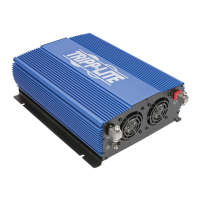
ON/OFF/REMOTE Switch: When you set the switch to the ON
(I) position, the Inverter provides AC power by converting DC
power from the connected 12V battery system. Set the switch to
the OFF (O) position to shut down the Inverter and conserve the
battery’s charge when you are not using connected equipment.
Also set the switch to the OFF position to reset the Inverter if
it has shut down due to overload or other critical events. Both
inverters are equipped with the capability to extend its ON/OFF
control to a remote location with the included PINVRM remote
panel. The remote provides ON/OFF operation and a status LED
to let you know the inverter is ON. See the Operation section for
more information.
D
LED Status Indicators: When the switch is set to the ON
position, the LED system will illuminate green during normal, low
voltage alarm and output short circuit conditions. If there is an
overload, over-temperature, or if a high/low DC voltage shutdown
condition occurs, the LED system will illuminate red.
LED
Operation
Status
Normal
Voltage
(12V)
Low
Voltage
Alarm
Low
Voltage
Shutdown
High
Voltage
Shutdown
Over-
Temperature
Output
Overload
Output
Short
Circuit
Green LED
Status
ON ON OFF OFF OFF OFF ON
Red LED
Status
OFF OFF ON ON ON ON OFF
Alarm OFF ON ON ON OFF OFF OFF
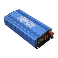
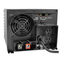
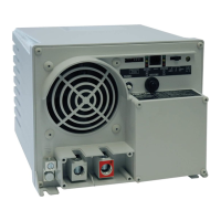
E
Temperature/Load-Controlled Cooling Fan: This fan regulates
the internal temperature of the inverter and prolongs service
life. It will only come on if the temperature or load demand goes
beyond the set thresholds.
F
DC Power Terminals: These positive and negative terminals
connect to the battery via the included or user-supplied cabling.
See Battery Connection for instructions.
19-04-283-9338A1.indb 7 5/2/2019 3:49:30 PM