9
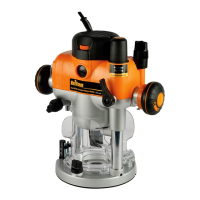
COLLET LOCK
1. Turn the power switch “off”, allowing
the retracting switch shutter to close.
(The retracting shutter will lock closed
when the collet lock is engaged.)
2. Place the router
upside down, or on its
side. With the motor
completely stopped
plunge the router to
its maximum depth
using the free plunge
or winder handle plunge mode.
Ensure the depth stop (24) is fully
retracted (see “Depth Stop
and Turret”). The collet should be
protruding through the base, allowing easy
spanner access.
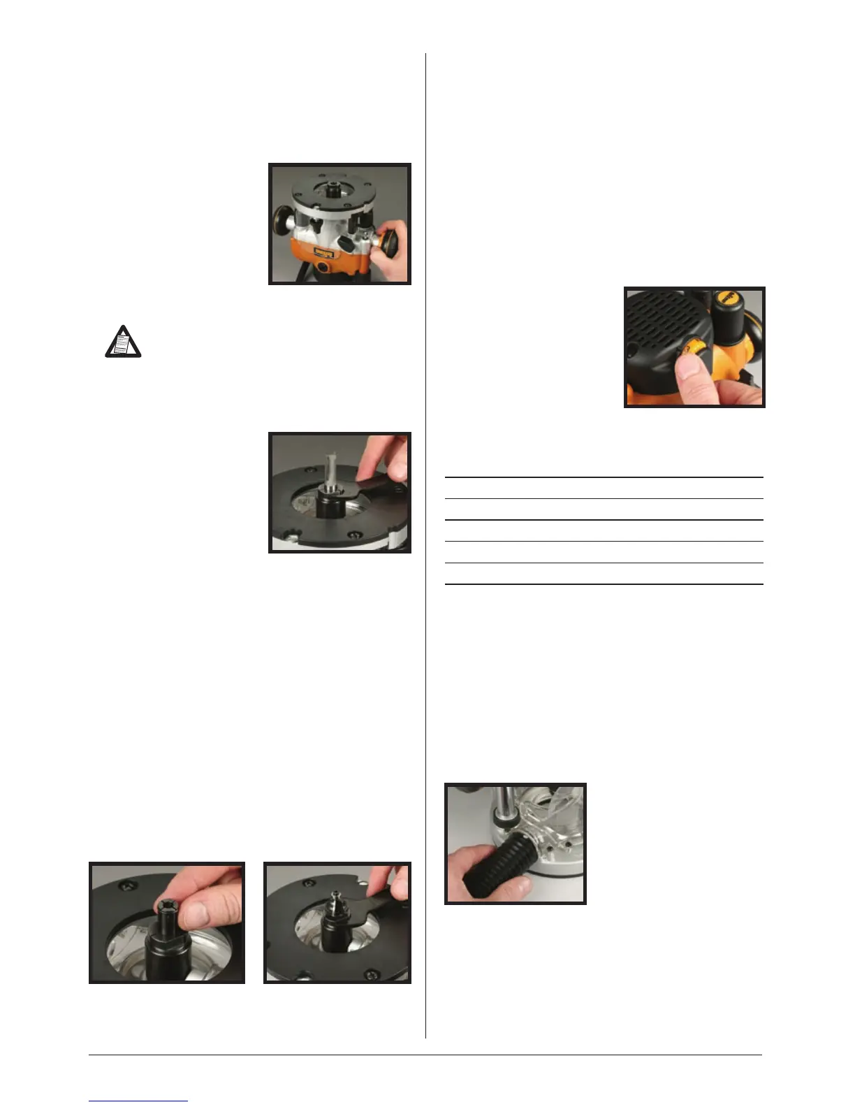
3. Insert your router
bit (21) fully into the
collet then use the
spanner (22) to turn
the collet slightly,
allowing the collet
lock to engage. Once
engaged, turn the spanner clockwise to
tighten the cutter.
4. Return the router to a normal operating
depth. This will disengage the collet lock
and release the retracting switch shutter,
enabling access to the power switch.
REDUCING SLEEVE
A reducing sleeve (10) is supplied for use of
small shanked (eg. ¼”) cutters.
With the router collet locked (see above),
place the reducing sleeve into the collet.
Fit your small shanked router bit into the
collet and tighten into position.
VARIABLE SPEED CONTROL
Router speed settings are not critical
- generally the highest speed which does
not result in burn marks on the workpiece
should be used. Where stated, always follow
the cutter manufacturers’ maximum speed
limitations.
Operating at reduced speed increases the
risk of damage to the router as a result of
overload. Use very slow feed rates and/or
multiple shallow cuts.
The Speed Controller
(13) is marked 1 to
5, corresponding
approximately with
the speeds and cutter
diameters below. Turn
the dial to select the
desired speed.
Setting RPM Cutter Diameter
5 21,000 Up to 25mm (1”)
4 18,000 25 - 50mm (1” - 2”)
3 14,500 50 - 65mm (2” - 2
1
/
2
”)
2 11,000 Over 65mm (2
1
/
2
”)
1 8,000 Use only if burning
DUST EXTRACTION
Dust Port
The Triton Router is equipped with a Dust
Port (20) for chip extraction above the cut.
It accepts 38mm (1½") O.D. hose, supplied
with the Triton Dust Collector (DCA300).
The hose screws into position via a left hand
thread (anti-clockwise).
Functions

 Loading...