T80si pumped
9
Screw the two upper fixing screws into position
leaving the base of the screw heads protruding
6 mm out from the wall.
Hook the backplate over the top screws and fit
the lower fixing screw into position.
DO NOT fully tighten the screws at this stage,
as the fixing holes are elongated to allow for
out of square adjustment after the plumbing
connections have been completed.
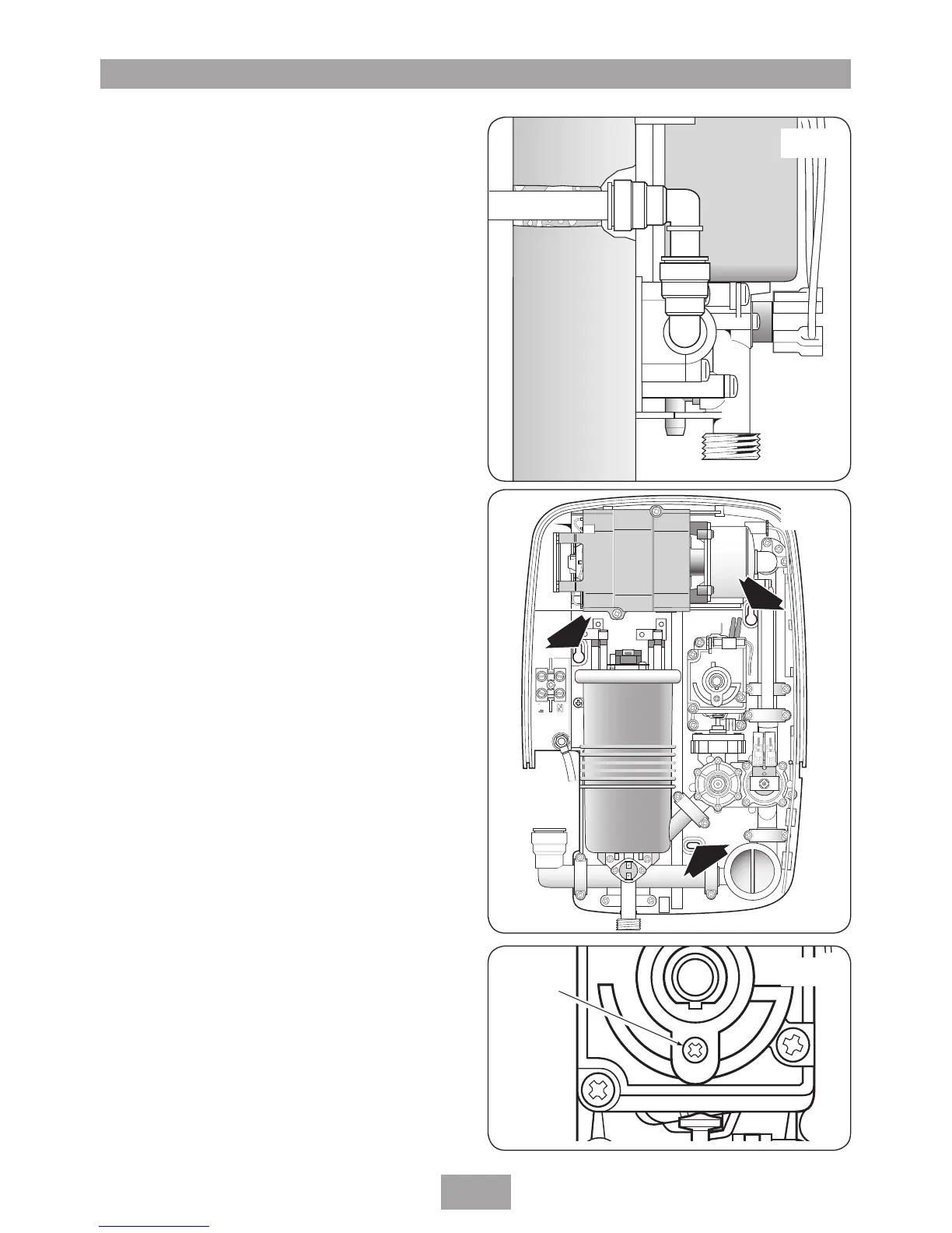
Note: A temporary factory fitted locking screw is
fitted to the power selector spindle (fig.12). This
is to make sure the spindle is held in the COLD
position while the commissioning procedure is
carried out. DO NOT remove the locking screw
before this procedure is completed.
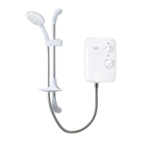
Fig.10
Fig.11
 Loading...