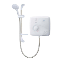
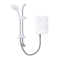
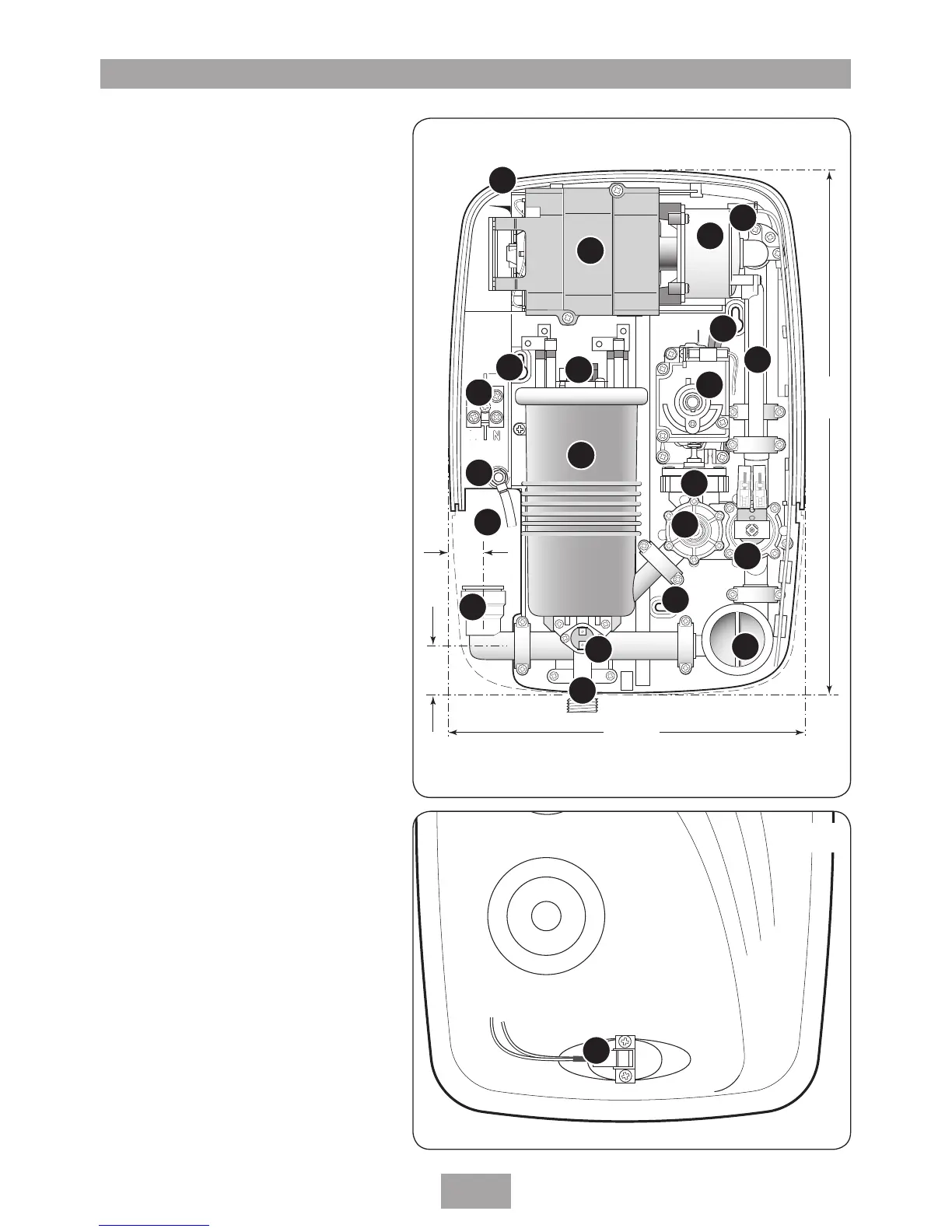
Fig.1
Inside unit (fig.1)
1. Top cable/pipe entry
2. Motor unit
3. Pump unit
4. Bleed screw
5. Wall screw fixing
6. Feed pipe
7. Thermal safety cut-out (main)
8. Terminal block
9. Can and element assembly
10. Power selector
11. Pressure switch
12. Temperature valve
13. Solenoid valve
14. Earth connection
15. Rear pipe / cable entry area
16. Inlet elbow
17. Thermal cut-out (outlet)
18. Outlet pipe
19. Filter
Inside cover (fig.2)
20. Start/Stop switch
Other items
Screw fixing kit
Instructions, guarantee, etc.
Fig.2
NOTE: Not all wires have been depicted for reasons of clarity
1
2
3
4
5
6
7
8
9
10
11
12
13
14
15
16
17
18
19
20
5
5
 Loading...