EasyManuals Logo

Triton T90xr User Manual

Triton T90xr
29 pages
To Next Page IconTo Next Page
To Previous Page IconTo Previous Page
Page #5 background imageLoading...
Page #5 background image
3
T90xr pumped electric shower
1. Top pipe / cable entry
2. Motor assembly
3. Pump assembly
4. Bleed screw
5. Wall screw fixing
6. Power selector assembly
7. Thermal cut-out (main)
8. Terminal block
9. Can and element assembly
10. Area for bottom and back pipe/cable entry
11. Pressure switch
12. Temperature valve
13. Solenoid valve
14. Earth connection
15. Inlet pipe
16. Filter
17. Thermal cut-out (outlet)
18. Outlet pipe
19. Trimplate
Other items
Screw fixing kit
Instructions, guarantee, etc.
Main components
MAIN COMPONENTS
268 mm
330 mm
157 mm
49 mm
58 mm
NOTE: Not all wiring shown for reasons of clarity
Inside unit (fig.1)
I-001-A
IMPORTANT: When first installed the unit
will be empty. It is essential the unit should
contain water before the elements are
switched on. It is vital that the
commissioning procedure is followed.
Failure to carry out this operation will result
in damage to the unit and will invalidate the
guarantee.
Fig.1
1
2
16
3
18
17
4
5
6
7
8
9
10
11
12
13
14
15
5
5
5
19
5

Questions and Answers:

Question and Answer IconNeed help?

Do you have a question about the Triton T90xr and is the answer not in the manual?
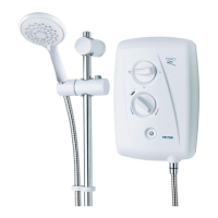
Triton T90xr Specifications

General IconGeneral
TypeElectric Shower
Power Ratings8.5kW, 9.5kW
Temperature ControlStabilised
Shower Head Spray Patterns5
FinishWhite
Warranty2 years
Water Entry PointsTop, Bottom, Back
Cable Entry PointsTop, Bottom, Back
InstallationWall Mounted
Water PressureMinimum 1 bar, Maximum 10 bar
Spray Modes5
Shower Hose Length1.25 meters

Related product manuals