19
ASSEMBLY STEPS
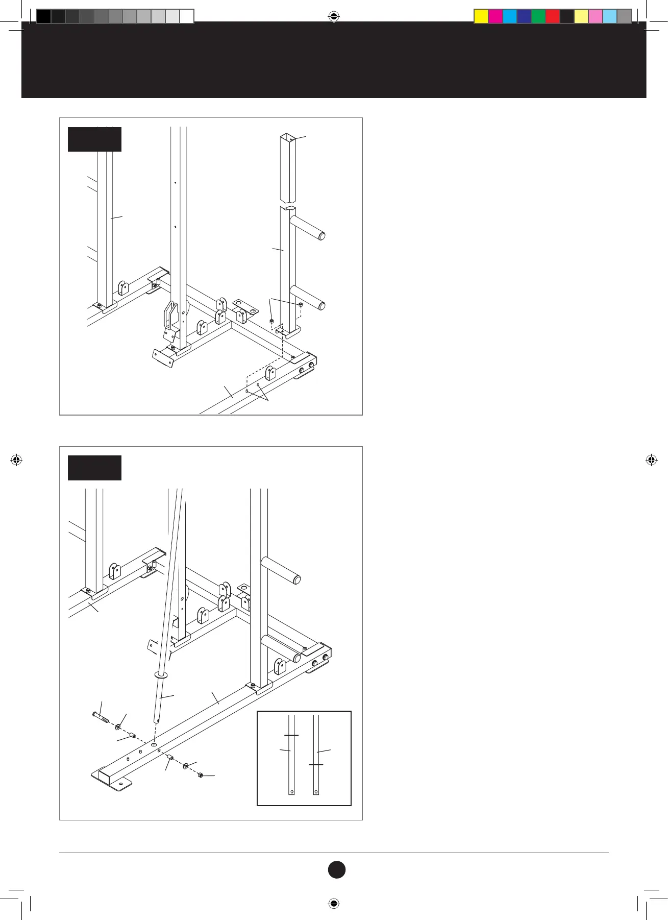
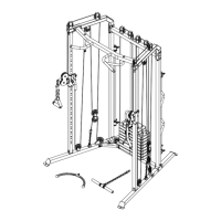
STEP 5:
1. Attach the Left Support (6) to the left Base (1)
with the indicated two M10 x 65 mm Carriage.
2. Bolts (83) and two M10 Locknuts (79).
Do not tighten the Locknuts yet.
3. Repeat this step with the Right Support (7).
STEP 6:
1. See the inset drawing. Identify the Weight Bar
Guides (5) and the Carriage Guides (64).
2. Attach a Weight Bar Guide (5) to the left Base
(1) with an M10 x 90 mm Bolt (89), two M10
Washers (84), two 25 mm Spacers (55), and an
M10 Locknut (79).
Do not tighten the Locknut yet.
3. Repeat this step with the other Weight Bar
Guide (not shown).
6
Hole
1
79
7
83
STEP 6
STEP 5
89
84
55
5
1
1
84
55
79
5
64
1
1
79
79
1
83
6
Hole
7
84
84
89
55
5
55
5 64
#21M05T035 Multifunction Smith Machine UM A4.indd 19 2021/06/24 11:27 AM