10253 - 8
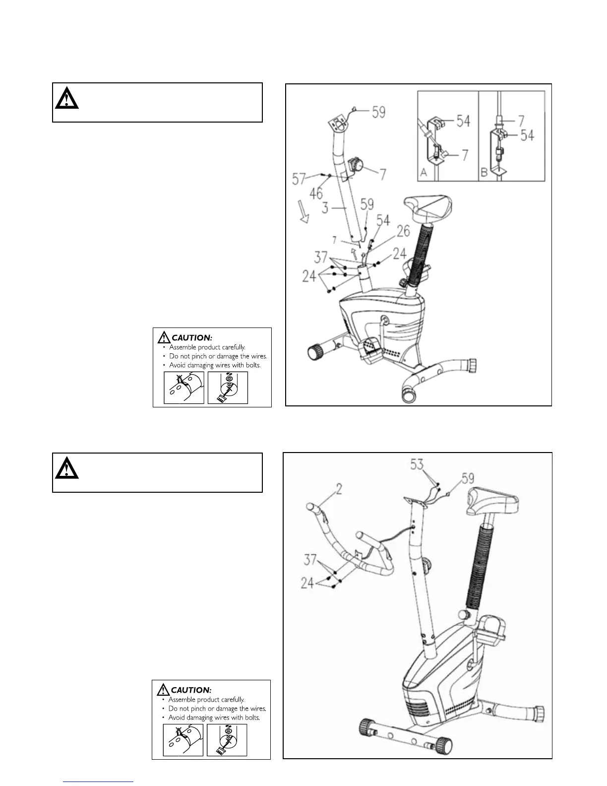
• RemovefourM8x15Bolts(24)andfourØ8
Curved Washers (37) from the tube of the Main
Frame (1).
• ConnecttheSensorWire(26)intheMainFrame
(1) to the Middle Section Sensor Wire (59) which
is in the Handlebar Post (3). Put the cable end of
the resistance cable of the Tension Control Knob
(7)intothespringhookoftheTensionCable(54)
as shown in drawing A. Pull the resistance cable
of Tension Control Knob (54) up and force it into
thegapofthemetalbracketoftheTensionCable
(54) as shown in drawing B .
• PlacetheHandlebarPost(3)ontothetubeof
theMainFrame(1)andsecurewithfourM8x15
Bolts (24) and four Ø8 Curved Washers (37) that
were previously removed.
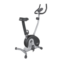
STEP 4: HANDLEBAR ASSEMBLY.
• RemovetwoM8x15Bolts(24)andtwoØ8
Curved Washers (64) from the Handlebar
Post (3).
• InserttheHandPulseSensorWires(53)into
the hole on the Handlebar Post (3) and then pull
them out the top end of the Handlebar Post (3).
• AttachtheHandlebar(2)ontotheHandlebar
Post(3)withtwoM8x15Bolts(24)andtwo
Ø8 Curved Washers (37) that were previously
removed.
CAUTION:
Ensure that cables are not damaged
during assembly or when tightening screws.
CAUTION:
Ensure that cables are not damaged
during assembly or when tightening screws.
4. ASSEMBLY STEPS
STEP 3: HANDLEBAR POST ASSEMBLY