10253 - 9
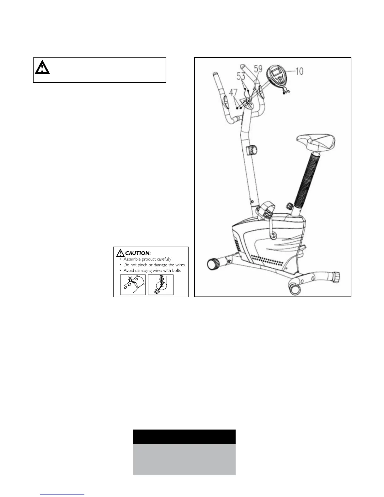
STEP 5: COMPUTER ASSEMBLY
• RemovetwoM5x10Bolts(47)fromthe
Computer (10).
• ConnecttheHandPulseSensorWires(53)and
Middle Section Sensor Wire (59) to the wires that
come from the Computer (10).
• AttachtheComputer(10)ontothetopendofthe
HandlebarPost(3)withthetwoM5x10Bolts(47)
that were previously removed.
4. ASSEMBLY STEPS
Recheck
all bolts and nuts are
tightened securely
before using the machine
CAUTION:
Ensure that cables are not damaged
during assembly or when tightening screws.