12
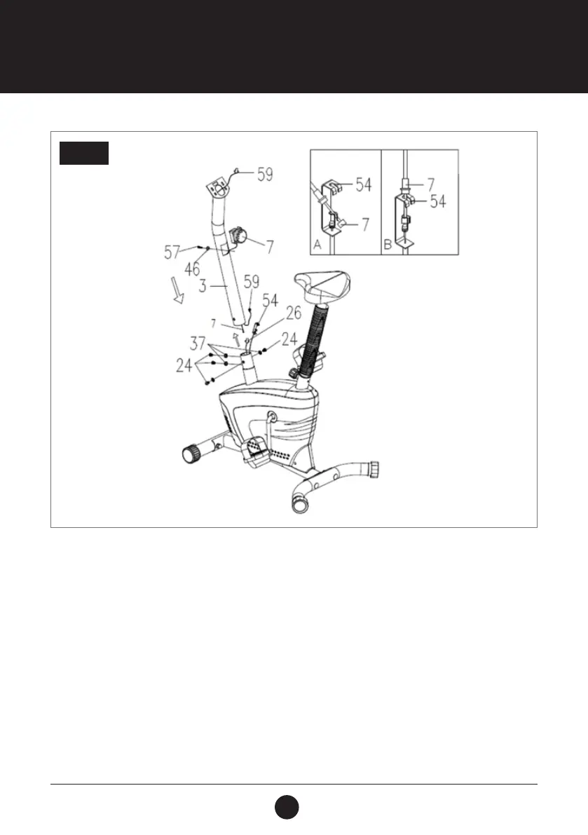
ASSEMBLY STEPS
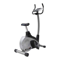
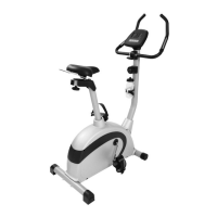
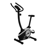
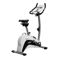
STEP 3: HANDLEBAR POST ASSEMBLY
Remove 4 Bolts (M8 x 15 S6) (24) and 4 Curved Washers (Ø20 x Ø8 x 1.5) (37) from the tube of the Main Frame (1).
Connect the Sensor Wire (L = 450 mm) (26) in the Main Frame (1) to the Middle Section Sensor Wire (L = 800) (59) which
is in the Handlebar Post (Ø50 x 1.5) (3). Put the cable end of the resistance cable of the Tension Control Knob (7) into the
spring hook of the Tension Cable (L = 600 mm) (54) as shown in drawing A. Pull the resistance cable of Tension Control
Knob (L = 600 mm) (54) up and force it into the gap of the metal bracket of the Tension Cable (L = 600 mm) (54) as
shown in drawing B.
Place the Handlebar Post (Ø50 x 1.5) (3) onto the tube of the Main Frame (1) and secure with 4 Bolts (M8 x 15 S6) (24)
and 4 Curved Washers (Ø20 x Ø8 x 1.5) (37) that were previously removed.
STEP 3