13
ASSEMBLY STEPS
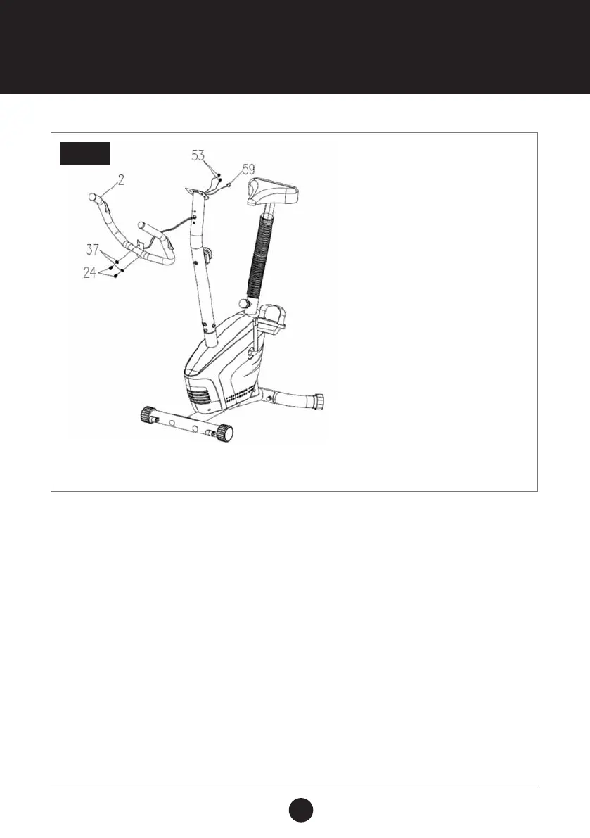
STEP 4: HANDLEBAR ASSEMBLY
Remove 2 Bolts (M8 x 15 S6) (24) and 2 Curved Washers (Ø16 x Ø8 x 1.5) (64) from the Handlebar Post (Ø50 x 1.5) (3).
Insert the Hand Pulse Sensor with Wire (L = 750 mm) (53) into the hole on the Handlebar Post (Ø50 x 1.5) (3) and then
pull them out the top end of the Handlebar Post (Ø50 x 1.5) (3).
Attach the Handlebar (Ø25 x 1.5) (2) onto the Handlebar Post (Ø50 x 1.5) (3) with 2 Bolts (M8 x 15 S6) (24) and 2 Curved
Washers (Ø20 x Ø8 x 1.5) (37) that were previously removed.
STEP 4