3
Operating manual
TROX air terminal units
Type VFC volume ow controllers
VFC
For technical and acoustic data on VFC series volume
ow controllers, refer to the control units catalogue.
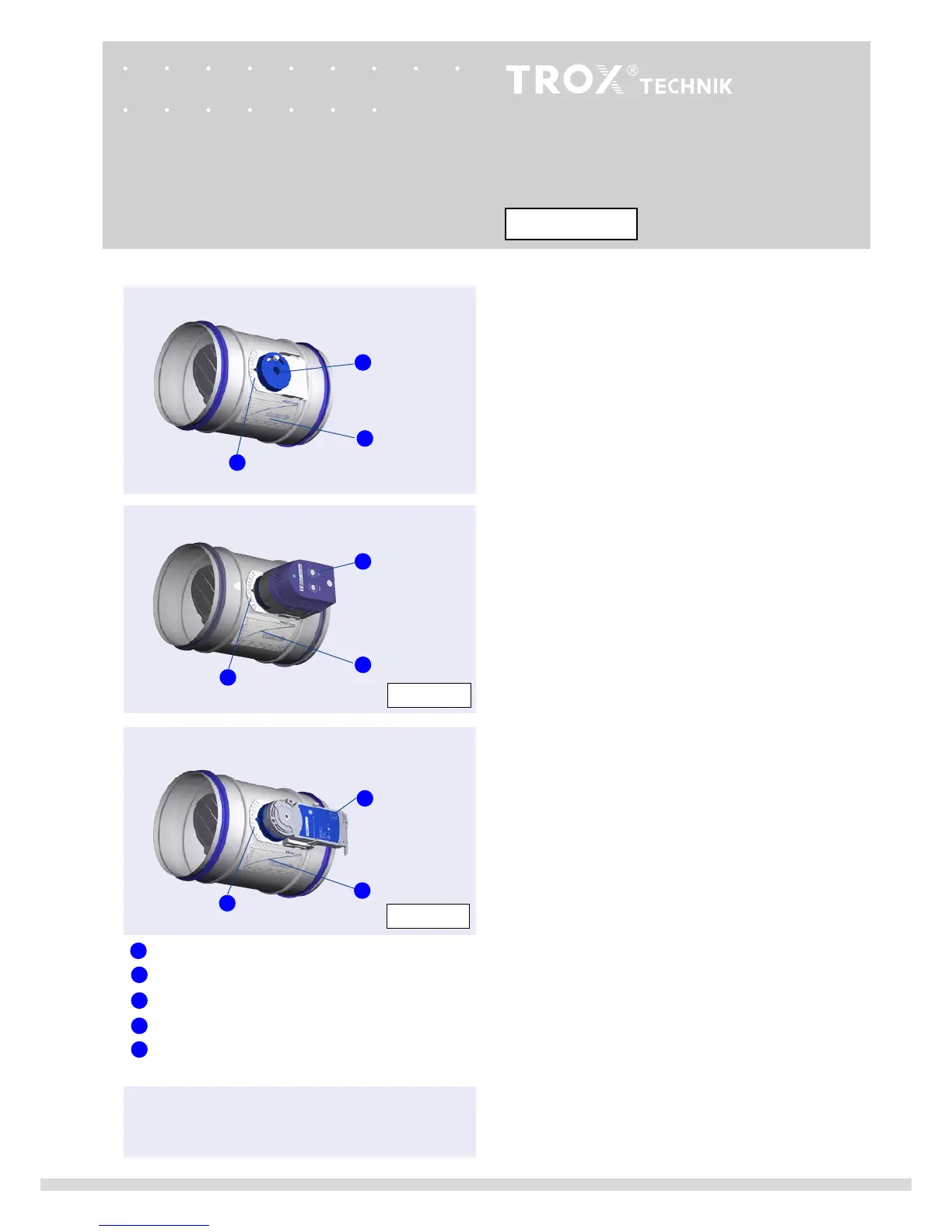
1
Adjustment scale
Volume ow rate characteristic
Rotary knob
Actuator, volume ow rate is set on potentiometers
Actuator, volume ow rate is set with mechanical stops
E01 ... E03
M01 ... M02
• For constant air ow rate
• Volume ow rate is set on site using the rotary knob
• Factory setting 5
Actuator E01, E02, E03
• For variable airow rate or
min
-
max
switching
• Volume ow rate is set on potentiometers
• Shut-o down to leakage airow is possible (setting 0)
• Height of the actuator 85 mm
• Factory settings:
min
= 4
max
= 8
Actuator M01, M02
• For
min
-
max
switching
• Volume ow rate is set using mechanical stops
• Shut-o down to leakage airow is possible (setting 0)
• Flat design, height of the actuator 35 mm
min
-
max
switching, actuator with mechanical
stops
Variable volume ow rate, actuator with
potentiometers
Constant volume ow rate
Product description
1
1
2
1
2
2
3
4
5
5
4
2
3