4
VFC
Operating manual
TROX air terminal units
Type VFC volume ow controllers
VFC
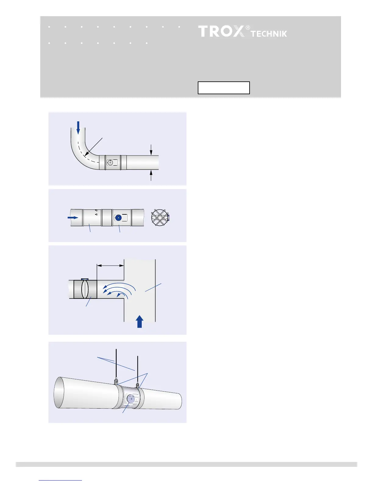
Installation
1.5 D
VFC
VFC
Manifold
Installation in a branch
Connection with ducting
Installation behind a bend
Combination with volume ow rate measuring unit
VFC
Suspension
D
min. 1 D
Connection
elements, e.g.
tube clamp with
rubber seal
Installation location and type of connection
• Select the installation location so the scale and
characteristic of the controller remain accessible.
• With reference to the characteristic, set the pointer to the
required volume ow rate.
• Horizontal or vertical controller installation.
• Note the airow direction according to the arrow on the
characteristic.
• Note for installation in front of and behind elbows, aps
or other obstacles with aerodynamic and acoustic eects.
• Horizontal or vertical installation; in combination with
volume ow rate measuring unit (VMR), arrange the sensor
tubes at 45° oset from the controller axis.
• Installation behind a bend:
Maintain a curvature radius of at least 1D unless there
is an additional straight inow length.
• Direct connection to a main duct/manifold: Maintain at least
1.5 D straight inow length
• Shorter inow lengths result in tighter tolerances.
• Direct connection to a main duct is permitted without
perforated sheet metal in extract air operation.
• Free intake not permitted, inow length 1.5 D required.
Inow nozzles are recommended in order to reduce the
pressure losses.
Connection with ducting
The connection diameters are appropriate for tubes
according to EN 1506 or EN 13180.
• No drilling work is allowed to be performed on the
controller!
• Before connecting the controllers, check the ducting
for contamination.
• Use standard TROX lip seals for connecting to the ducting.
VMR