6
Operating manual
TROX air terminal units
Type VFC volume ow controllers
Actuator E01 ... E03
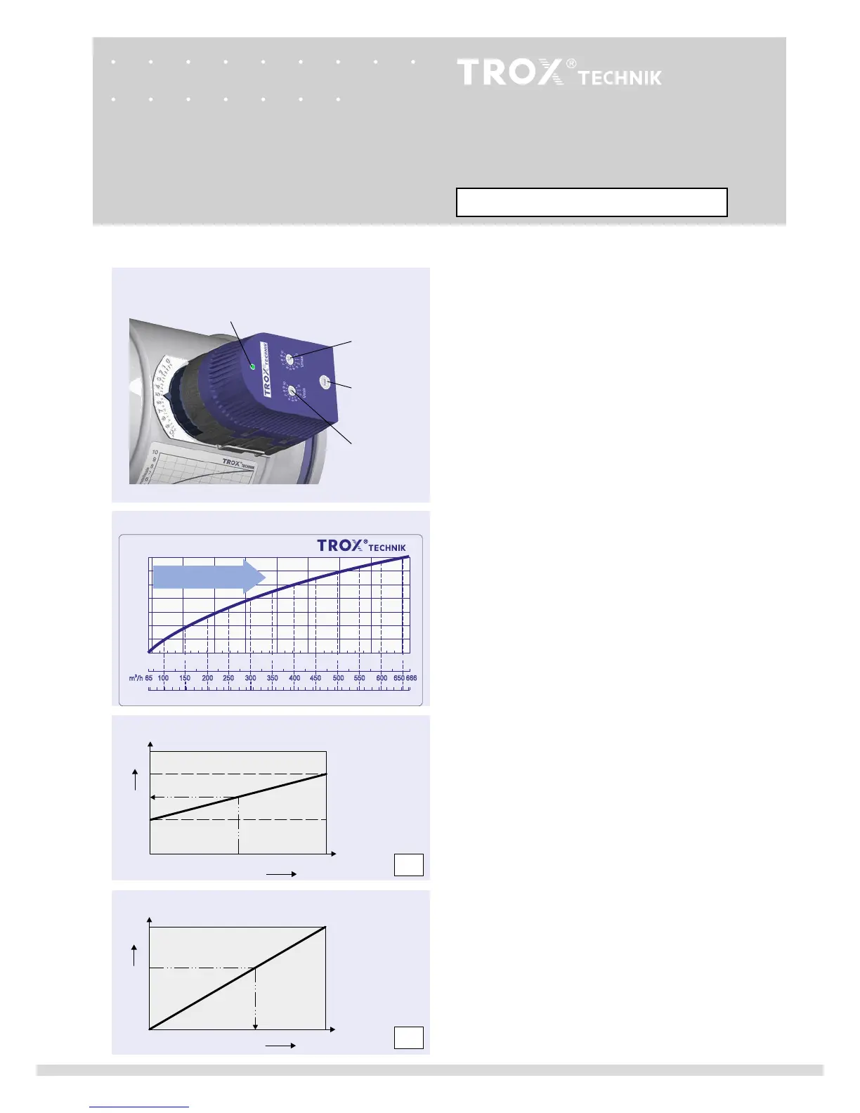
Setting the set ow rate
Each VFC carries a characteristic to determine the setting
values on site (see example, nominal size 160).
min
values below 3 results in an unregulated airow dependent
on the duct pressure that is not less than
min-unit
.
Set the set ow rate as follows:
• Determine the setting value for the set ow rate from the
characteristic or the table on page 5.
• Set the values on the
min
- and
max
potentiometers.
• Factory setting:
min
= 4
max
= 8
• Shut-o down to leakage airow is possible, value to be set 0
Functional test
A functional test can be performed very easily using the service
button and the indicator light.
• Press service button for at least 1 second
• Actuator turns toward
min
• Actuator turns toward
max
• Actuator returns to control mode
Indicator light provides functional information
• Permanently on : Position set
• Flashing once a second : Actuator operating
• Flashing twice a second : Actuator is jammed and stationary
• O : No supply voltage
Actuator E03
The relationships between the setting value and output signal
U, or control signal w, are shown in the two characteristics on
the left.
The output signal does not correspond to the currently
measured volume flow rate, but reflects the setpoint value.
Example:
Factory set values:
min
= 4
min
= 8
Required value: 6
--> Required control signal: 5 V
Available output signal: 6 V corresponding to set value 6
max
potentiometer
Indicator light
Service button
min
potentiometer
Variable volume ow rate operation, actuator with
potentiometers
Characteristic for determining the volume ow rate
0
6
10
0
6 V
10 VDC
0
6
4
8
10
max
min
05 V 10 VDC
Characteristic of the actual value signal
Characteristics of the control signal
Output signal U
Control signal w
Value to be set
Value to be set
E03
E03